
Engineering Mechanics: Statics
13th Edition
ISBN: 9780132915540
Author: Russell C. Hibbeler
Publisher: Prentice Hall
expand_more
expand_more
format_list_bulleted
Videos
Textbook Question
Chapter 6.3, Problem 4P
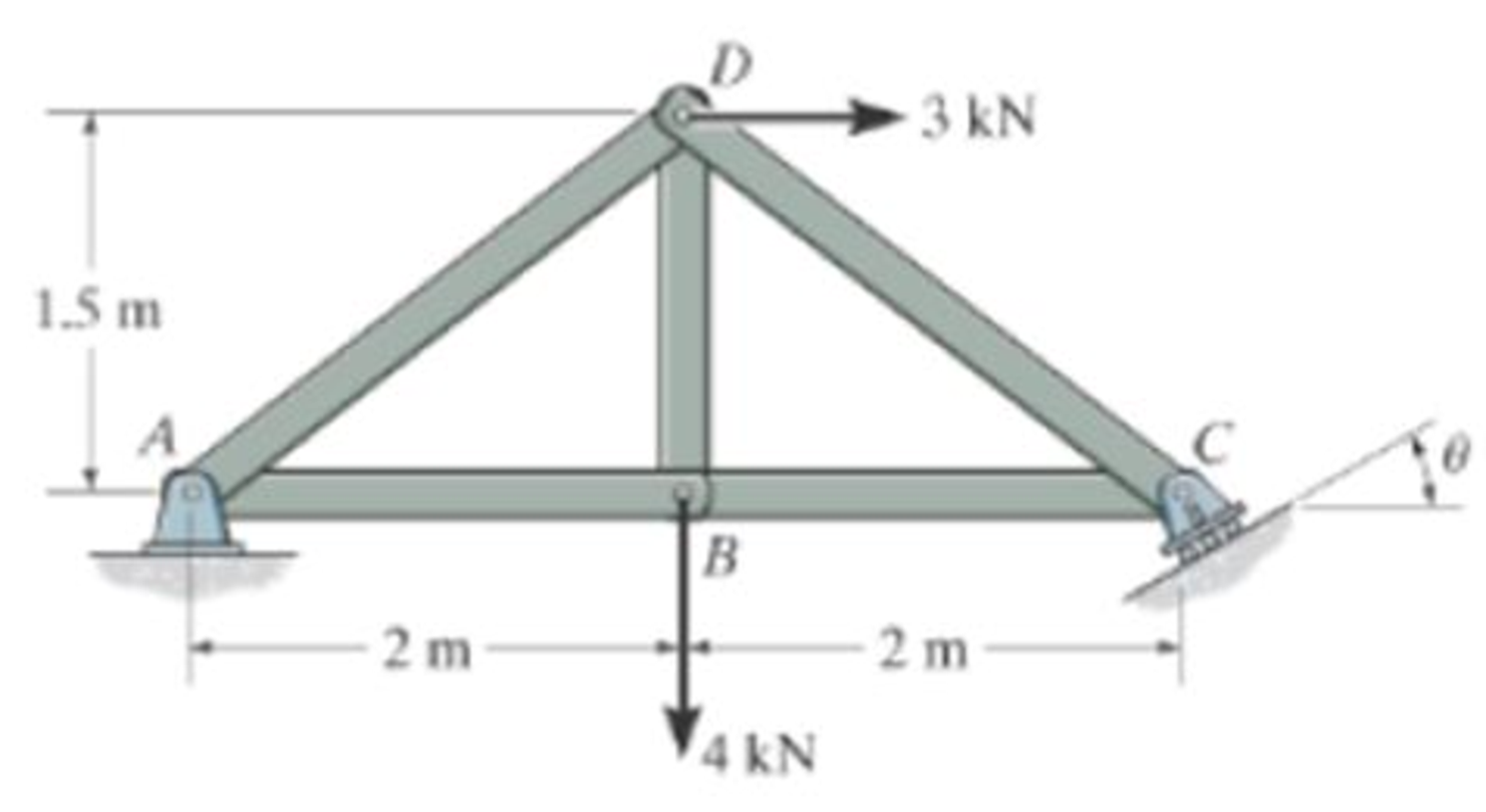
Determine the force in each member of the truss, and state if the members are in tension or compression Set θ = 30°.
Probs. 6-6
Expert Solution & Answer

Learn your wayIncludes step-by-step video

schedule11:32
Students have asked these similar questions
Please do not use any AI tools to solve this question.
I need a fully manual, step-by-step solution with clear explanations, as if it were done by a human tutor.
No AI-generated responses, please.
Please do not use any AI tools to solve this question.
I need a fully manual, step-by-step solution with clear explanations, as if it were done by a human tutor.
No AI-generated responses, please.
Please do not use any AI tools to solve this question.
I need a fully manual, step-by-step solution with clear explanations, as if it were done by a human tutor.
No AI-generated responses, please.
Chapter 6 Solutions
Engineering Mechanics: Statics
Ch. 6.3 - State if the members are in tension or...Ch. 6.3 - State if the members are in tension or...Ch. 6.3 - Prob. 3FPCh. 6.3 - Determine the greatest load P that can be applied...Ch. 6.3 - Identify the zero-force members in the truss....Ch. 6.3 - State if the members are in tension or...Ch. 6.3 - Prob. 1PCh. 6.3 - Prob. 2PCh. 6.3 - Determine the force in each member of the truss,...Ch. 6.3 - Determine the force in each member of the truss,...
Ch. 6.3 - Prob. 5PCh. 6.3 - Determine the force in each member of the truss...Ch. 6.3 - Determine the force in each member of the Pratt...Ch. 6.3 - Prob. 8PCh. 6.3 - Prob. 9PCh. 6.3 - Prob. 10PCh. 6.3 - Determine the force in each member of the truss...Ch. 6.3 - Prob. 12PCh. 6.3 - Prob. 13PCh. 6.3 - Prob. 14PCh. 6.3 - Prob. 15PCh. 6.3 - State whether the members are in tension or...Ch. 6.3 - If the maximum force that any member can support...Ch. 6.3 - Prob. 18PCh. 6.3 - Prob. 19PCh. 6.3 - Prob. 20PCh. 6.3 - Prob. 21PCh. 6.3 - Determine the force in each member of the double...Ch. 6.3 - Prob. 23PCh. 6.3 - Prob. 24PCh. 6.3 - Prob. 25PCh. 6.3 - Prob. 26PCh. 6.4 - Determine the force in members BC, CF, and FE....Ch. 6.4 - State if the members are in tension or...Ch. 6.4 - State if the members are in tension or...Ch. 6.4 - State if the members are in tension or...Ch. 6.4 - State if the members are in tension or...Ch. 6.4 - State if the members are in tension or...Ch. 6.4 - Determine the force in members HG, HE and DE of...Ch. 6.4 - Prob. 28PCh. 6.4 - Prob. 29PCh. 6.4 - Prob. 30PCh. 6.4 - State if these members are in tension or...Ch. 6.4 - State if these members are in tension or...Ch. 6.4 - Prob. 33PCh. 6.4 - Prob. 34PCh. 6.4 - State if these members are in tension or...Ch. 6.4 - Determine the force in members CD, CF, and CG and...Ch. 6.4 - Determine the force in members GF, FB, and BC of...Ch. 6.4 - Prob. 38PCh. 6.4 - Prob. 39PCh. 6.4 - Prob. 40PCh. 6.4 - Prob. 41PCh. 6.4 - Prob. 42PCh. 6.4 - Prob. 43PCh. 6.4 - Prob. 44PCh. 6.4 - Prob. 45PCh. 6.4 - Prob. 46PCh. 6.4 - Prob. 47PCh. 6.4 - Prob. 48PCh. 6.4 - Prob. 49PCh. 6.6 - Determine the force P needed to hold the 60-lb...Ch. 6.6 - Determine the horizontal and vertical components...Ch. 6.6 - If a 100-N force is applied to the handles of the...Ch. 6.6 - Prob. 16FPCh. 6.6 - Determine the normal force that the 100-lb plate A...Ch. 6.6 - Also, determine the proper placement x of the hook...Ch. 6.6 - Determine the components of reaction at A and B....Ch. 6.6 - Determine the reactions at D. Prob. F6-20Ch. 6.6 - Determine the components of reaction at A and C....Ch. 6.6 - Determine the components of reaction at C. Prob....Ch. 6.6 - Determine the components of reaction at E. Prob....Ch. 6.6 - Determine the components of reaction at D and the...Ch. 6.6 - The block weighs 100 lb. Prob. 6-62Ch. 6.6 - Prob. 62PCh. 6.6 - Prob. 63PCh. 6.6 - Prob. 64PCh. 6.6 - Prob. 65PCh. 6.6 - Prob. 66PCh. 6.6 - Prob. 67PCh. 6.6 - Prob. 68PCh. 6.6 - Also, what are the horizontal and vertical...Ch. 6.6 - Prob. 70PCh. 6.6 - Prob. 71PCh. 6.6 - Prob. 72PCh. 6.6 - Prob. 73PCh. 6.6 - Determine the horizontal and vertical components...Ch. 6.6 - Determine the horizontal and vertical components...Ch. 6.6 - Prob. 76PCh. 6.6 - Prob. 77PCh. 6.6 - Prob. 78PCh. 6.6 - The toggle clamp is subjected to a force F at the...Ch. 6.6 - Determine the force P exerted on each of the...Ch. 6.6 - Prob. 81PCh. 6.6 - Determine the force in the guy cable AI and the...Ch. 6.6 - Prob. 83PCh. 6.6 - Prob. 84PCh. 6.6 - Prob. 85PCh. 6.6 - If the wheel at A exerts a normal force of FA = 80...Ch. 6.6 - Prob. 87PCh. 6.6 - Prob. 88PCh. 6.6 - Prob. 89PCh. 6.6 - Determine the force that the jaws J of the metal...Ch. 6.6 - When the walking beam ABC is horizontal, the force...Ch. 6.6 - Prob. 92PCh. 6.6 - Prob. 93PCh. 6.6 - Determine the total force he must exert on bar AB...Ch. 6.6 - Determine the total force he must exert on bar AB...Ch. 6.6 - Prob. 96PCh. 6.6 - Prob. 97PCh. 6.6 - Determine the horizontal and vertical components...Ch. 6.6 - If a clamping force of 300 N is required at A,...Ch. 6.6 - If a force of F = 350 N is applied to the handle...Ch. 6.6 - Prob. 101PCh. 6.6 - Prob. 102PCh. 6.6 - Prob. 103PCh. 6.6 - Prob. 104PCh. 6.6 - Prob. 105PCh. 6.6 - If d = 0.75 ft and the spring has an unstretched...Ch. 6.6 - If a force of F = 50 lb is applied to the pads at...Ch. 6.6 - Determine the force in the hydraulic cylinder AB...Ch. 6.6 - Prob. 109PCh. 6.6 - Prob. 110PCh. 6.6 - Prob. 111PCh. 6.6 - If the sprig has a stiffness of k = 15 lb/in., and...Ch. 6.6 - Prob. 113PCh. 6.6 - Prob. 114PCh. 6.6 - If only vertical forces are supported at the...Ch. 6.6 - Determine the resultant forces at pins B and C on...Ch. 6.6 - Determine the force in each member of the truss...Ch. 6.6 - Determine the horizontal and vertical components...Ch. 6.6 - Prob. 123RPCh. 6.6 - Prob. 124RPCh. 6.6 - Prob. 125RPCh. 6.6 - Determine the force in each member of the truss...
Additional Engineering Textbook Solutions
Find more solutions based on key concepts
What output will be produced by the following code?
Java: An Introduction to Problem Solving and Programming (8th Edition)
Big data Big data describes datasets with huge volumes that are beyond the ability of typical database manageme...
Management Information Systems: Managing The Digital Firm (16th Edition)
Define each of the following terms: supertype subtype specialization entity cluster completeness constraint enh...
Modern Database Management
What is an object? What is a control?
Starting Out With Visual Basic (8th Edition)
Consider the following skeletal C program: void fun1(void); / prototype / void fun2(void); / prototype / void f...
Concepts Of Programming Languages
In Exercises 41 through 46, identify the errors.
Introduction To Programming Using Visual Basic (11th Edition)
Knowledge Booster


Learn more about
Need a deep-dive on the concept behind this application? Look no further. Learn more about this topic, mechanical-engineering and related others by exploring similar questions and additional content below.Similar questions
- [Q2]: The cost information supplied by the cost accountant is as follows:Sales 20,00 units, $ 10 per unitCalculate the (a/ newsale guantity and (b) new selling price to earn the sameVariable cost $ 6 per unit, Fixed Cost $ 30,000, Profit $ 50,000profit ifi) Variable cost increases by $ 2 per unitil) Fixed cost increase by $ 10,000Ili) Variable cost increase by $ 1 per unit and fixed cost reduces by $ 10,000arrow_forwardcan you please help me perform Visual Inspection and Fractography of the attatched image: Preliminary examination to identify the fracture origin, suspected fatigue striation, and corrosion evidences.arrow_forwardcan you please help[ me conduct Causal Analysis (FTA) on the scenario attatched: FTA diagram which is a fault tree analysis diagram will be used to gain an overview of the entire path of failure from root cause to the top event (i.e., the swing’s detachment) and to identify interactions between misuse, material decay and inspection errors.arrow_forward
- hi can you please help me in finding the stress intensity factor using a k-calcluator for the scenario attathced in the images.arrow_forwardHi, can you please help me .Identify and justify suitable analytical techniques of the scenario below, bearing in mind the kinds of information being handled to reach a conclusion (methodology). A child swing set was discovered to have failed at the fixing at the top of the chains connecting the seat to the top of the swing set. A 12 mm threaded steel bolt, connecting the shackle to the top beam, failed at the start of the threaded region on the linkage closest to the outside side of the swing set . The linkage and bolts were made of electro galvanised mild steel . The rigid bar chain alternatives and fixings were of the same material and appeared to be fitted in accordance with guidelines. The yield strength of the steel used is 260 MPa and the UTS is 380 MPa. The bolt that failed was threaded using a standard thread with a pitch (distance between threads) of 1.75 mm and a depth of approximately 1.1 mm. The swing set in question had been assigned to ‘toddlers’ with the application of…arrow_forwardHi, can you please define and calculate the failure mode of the linkage that failed on the swing (images added) : A child swing set was discovered to have failed at the fixing at the top of the chains connecting the seat to the top of the swing set. A 12 mm threaded steel bolt, connecting the shackle to the top beam, failed at the start of the threaded region on the linkage closest to the outside side of the swing set . The linkage and bolts were made of electro galvanised mild steel . The rigid bar chain alternatives and fixings were of the same material and appeared to be fitted in accordance with guidelines. The yield strength of the steel used is 260 MPa and the UTS is 380 MPa. The bolt that failed was threaded using a standard thread with a pitch (distance between threads) of 1.75 mm and a depth of approximately 1.1 mm. The swing set in question had been assigned to ‘toddlers’ with the application of a caged-type seat. However, the location was within the play area not…arrow_forward
- Page 11-68. The rectangular plate shown is subjected to a uniaxial stress of 2000 psi. Compute the shear stress and the tensile developed on a plane forming an angle of 30° with the longitud axis of the member. (Hint: Assume a cross-sectional area of unity) 2000 psi 2000 psi hparrow_forward11-70. A shear stress (pure shear) of 5000 psi exists on an element. (a) Determine the maximum tensile and compressive stresses caused in the element due to this shear. (b) Sketch the element showing the planes on which the maximum tensile and compressive stresses act.arrow_forward11-20. An aluminum specimen of circular cross section, 0.50 in. in diameter, ruptured under a tensile load of 12,000 lb. The plane of failure was found to be at 48° with a plane perpendicular to the longitudinal axis of the specimen. (a) Compute the shear stress on the failure plane. (b) Compute the maximum tensile stress. (c) Compute the tensile stress on the failure plane. hparrow_forward
- A long flat steel bar 13 mm thick and 120 mm wide has semicircular grooves as shown and carries a tensile load of 50 kN Determine the maximum stress if plate r= 8mm r=21mm r=38mmarrow_forwardProblem 13: F₁ = A =250 N 30% Determine the moment of each of the three forces about point B. F₂ = 300 N 60° 2 m -3 m B 4 m F3=500 Narrow_forward3 kN 3 kN 1.8 kN/m 80 mm B 300 mm D an 1.5 m-1.5 m--1.5 m- PROBLEM 5.47 Using the method of Sec. 5.2, solve Prob. 5.16 PROBLEM 5.16 For the beam and loading shown, determine the maximum normal stress due to bending on a transverse section at C.arrow_forward
arrow_back_ios
SEE MORE QUESTIONS
arrow_forward_ios
Recommended textbooks for you
 Elements Of ElectromagneticsMechanical EngineeringISBN:9780190698614Author:Sadiku, Matthew N. O.Publisher:Oxford University Press
 Mechanics of Materials (10th Edition)Mechanical EngineeringISBN:9780134319650Author:Russell C. HibbelerPublisher:PEARSON
 Thermodynamics: An Engineering ApproachMechanical EngineeringISBN:9781259822674Author:Yunus A. Cengel Dr., Michael A. BolesPublisher:McGraw-Hill Education
 Control Systems EngineeringMechanical EngineeringISBN:9781118170519Author:Norman S. NisePublisher:WILEY
 Mechanics of Materials (MindTap Course List)Mechanical EngineeringISBN:9781337093347Author:Barry J. Goodno, James M. GerePublisher:Cengage Learning
 Engineering Mechanics: StaticsMechanical EngineeringISBN:9781118807330Author:James L. Meriam, L. G. Kraige, J. N. BoltonPublisher:WILEY
Elements Of Electromagnetics
Mechanical Engineering
ISBN:9780190698614
Author:Sadiku, Matthew N. O.
Publisher:Oxford University Press
Mechanics of Materials (10th Edition)
Mechanical Engineering
ISBN:9780134319650
Author:Russell C. Hibbeler
Publisher:PEARSON
Thermodynamics: An Engineering Approach
Mechanical Engineering
ISBN:9781259822674
Author:Yunus A. Cengel Dr., Michael A. Boles
Publisher:McGraw-Hill Education
Control Systems Engineering
Mechanical Engineering
ISBN:9781118170519
Author:Norman S. Nise
Publisher:WILEY
Mechanics of Materials (MindTap Course List)
Mechanical Engineering
ISBN:9781337093347
Author:Barry J. Goodno, James M. Gere
Publisher:Cengage Learning
Engineering Mechanics: Statics
Mechanical Engineering
ISBN:9781118807330
Author:James L. Meriam, L. G. Kraige, J. N. Bolton
Publisher:WILEY
Physics 33 - Fluid Statics (1 of 10) Pressure in a Fluid; Author: Michel van Biezen;https://www.youtube.com/watch?v=mzjlAla3H1Q;License: Standard YouTube License, CC-BY