
Concept explainers
Videos
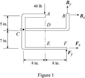
The 48-lb load can be moved along the line of action shown and applied at A, D, or E. Determine the components of the reactions at B and F if the 48-lb load is applied (a) at A, (b) at D, (c) at E.
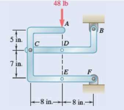
Fig. P6.88 and P6.89
SOLUTION
Free body: Entire frame:
The following analysis is valid for (a), (b) and (c) since the position of the load along its line of action is immaterial.
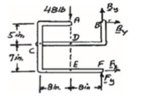
 ∑MF = 0: (48 lb)(8 in.) − Bx (12 in.) = 0
Bx = 32 lb Bx = 32 lb →
 ∑Fx = 0: 32 lb + Fx = 0
Fx = −32 lb Fx = 32 lb ←
+↑ ∑Fy = 0: By + Fy − 48 lb = 0 (1)
a) Load applied at A.
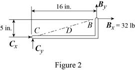
Free body: Member CDB
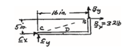
CDB is a two-force member. Thus, the reaction at B must be directed along BC.
From Eq. (1): 10 lb + Fy − 48 lb = 0
Fy = 38 lb Fy = 38 lb ↑
Thus reactions are:
Bx = 32.0 lb →, By = 10.00 lb ↑
Fx = 32.0 lb ←, Fy = 38.00 lb ↑
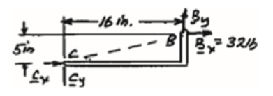
(b) Load applied at D.
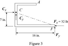
Free body: Member ACF.
ACF is a two-force member. Thus, the reaction at F must be directed along CF.
From Eq. (1): By + 14 lb – 48 lb = 0
By = 34 lb, By = 34 lb ↑
Thus, reactions are:
Bx = 32.0 lb ←, By = 34.00 lb ↑
Fx = 32.0 lb →, Fy = 14.00 lb ↑
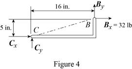
(c) Load applied at E.
Free body: Member CDB.
This is the same free body as in Part (a).
Reactions are same as (a)
(a)
The components of reaction at
Answer to Problem 6.88P
The components of reaction at
Explanation of Solution
The arrangement is shown in Fig. P6.88. The free-body diagram of the entire frame is given in Figure 1.
Write the expressions for equilibrium for the given system using the conditions on moments
The counter clockwise moments at
The sum of
The sum of
The load is applied at
Conclusion:
Apply the condition in equation (I) to the free-body diagram in Figure 1 and solve for
Apply the condition in equation (II) to the free-body diagram in Figure 1 and solve for
Apply the condition in equation (III) to the free-body diagram in Figure 1.
From the free-body diagram in Figure 2, write the expression connecting the components of the reaction
Substitute
Substitute
Therefore, the components of reaction at
(b)
The components of reaction at
Answer to Problem 6.88P
The components of reaction at
Explanation of Solution
The
The load is applied at
Conclusion:
From the free-body diagram in Figure 3, write the expression connecting the components of the reaction
Substitute
Substitute
Therefore, the components of reaction at
(c)
The components of reaction at
Answer to Problem 6.88P
The components of reaction at
Explanation of Solution
The
The load is applied at
Conclusion:
The free-body diagram of the member
Therefore, the components of reaction at
Want to see more full solutions like this?
Chapter 6 Solutions
VEC MECH 180-DAT EBOOK ACCESS(STAT+DYNA)


- Solve this problem and show all of the workarrow_forwardPlease do not rely too much on chatgpt, because its answer may be wrong. Please consider it carefully and give your own answer. You can borrow ideas from gpt, but please do not believe its answer.Very very grateful! Please do not copy other's work,i will be very very grateful!!Please do not copy other's work,i will be very very grateful!!arrow_forward= The frame shown is fitted with three 50 cm diameter frictionless pulleys. A force of F = 630 N is applied to the rope at an angle ◊ 43°. Member ABCD is attached to the wall by a fixed support at A. Find the forces indicated below. Note: The rope is tangent to the pully (D) and not secured at the 3 o'clock position. a b •C *су G E e d BY NC SA 2013 Michael Swanbom Values for dimensions on the figure are given in the following table. Note the figure may not be to scale. Variable Value a 81 cm b 50 cm с 59 cm d 155 cm For all answers, take x as positive to the right and positive upward. At point A, the fixed support exerts a force of: A = + ĴN and a reaction couple of: →> ΜΑ Member CG is in Select an answer magnitude У as k N-m. and carries a force of N.arrow_forward
- The lower jaw AB [Purple 1] and the upper jaw-handle AD [Yellow 2] exert vertical clamping forces on the object at R. The hand squeezes the upper jaw-handle AD [2] and the lower handle BC [Orane 4] with forces F. (Member CD [Red 3] acts as if it is pinned at D, but, in a real vise-grips, its position is actually adjustable.) The clamping force, R, depends on the geometry and on the squeezing force F applied to the handles. Determine the proportionality between the clamping force, R, and the squeezing force F for the dimensions given. d3 d4 R 1 B d1 2 d2 D... d5 F 4 F Values for dimensions on the figure are given in the following table. Note the figure may not be to scale. Variable Value d1 65 mm d2 156 mm d3 50 mm 45 d4 d5 113 mm 30 mm R = Farrow_forwardA triangular distributed load of max intensity w =460 N/m acts on beam AB. The beam is supported by a pin at A and member CD, which is connected by pins at C and D respectively. Determine the reaction forces at A and C. Enter your answers in Cartesian components. Assume the masses of both beam AB and member CD are negligible. cc 040 BY NC SA 2016 Eric Davishahl W A C D -a- B Ул -b- x Values for dimensions on the figure are given in the following table. Note the figure may not be to scale. Variable Value α 5.4 m b 8.64 m C 3.24 m The reaction at A is A = i+ ĴN. λ = i+ Ĵ N. The reaction at C is C =arrow_forward56 Clamps like the one shown are commonly used in woodworking applications. This clamp has the dimensions given in the table below the figure, and its jaws are mm thick (in the direction perpendicular to the plane of the picture). a.) The screws of the clamp are adjusted so that there is a uniform pressure of P = 150 kPa being applied to the workpieces by the jaws. Determine the force carried in each screw. Hint: the uniform pressure can be modeled in 2-D as a uniform distributed load with intensity w = Pt (units of N/m) acting over the length of contact between the jaw and the workpiece. b.) Determine the minimum vertical force (parallel to the jaws) required to pull either one of the workpieces out of the clamp jaws. Use a coefficient of static friction between all contacting surfaces of μs = 0.56 and the same clamping pressure given for part (a). 2013 Michael Swanbom A B C a Values for dimensions on the figure are given in the following table. Note the figure may not be to scale.…arrow_forward
- Determine the force in each member of the space truss given F=5 kN. Use positive to indicate tension and negative to indicate compression. F E Z -2 m. B 3 m C 5 m 3 m A -4 m. AB = KN FAC = FAD = KN KN KN FBC = KN FBD FBE = = KN Farrow_forwardA short brass cyclinder (denisty=8530 kg/m^3, cp=0.389 kJ/kgK, k=110 W/mK, and alpha=3.39*10^-5 m^2/s) of diameter 4 cm and height 20 cm is initially at uniform temperature of 150 degrees C. The cylinder is now placed in atmospheric air at 20 degrees C, where heat transfer takes place by convection with a heat transfer coefficent of 40 W/m^2K. Calculate (a) the center temp of the cylinder, (b) the center temp of the top surface of the cylinder, and (c) the total heat transfer from the cylinder 15 min after the start of the cooling. Solve this problem using the analytical one term approximation method. (Answer: (a) 45.7C, (b)45.3C, (c)87.2 kJ)arrow_forwardA short brass cyclinder (denisty=8530 kg/m^3, cp=0.389 kJ/kgK, k=110 W/mK, and alpha=3.39*10^-5 m^2/s) of diameter 4 cm and height 20 cm is initially at uniform temperature of 150 degrees C. The cylinder is now placed in atmospheric air at 20 degrees C, where heat transfer takes place by convection with a heat transfer coefficent of 40 W/m^2K. Calculate (a) the center temp of the cylinder, (b) the center temp of the top surface of the cylinder, and (c) the total heat transfer from the cylinder 15 min after the start of the cooling. Solve this problem using the analytical one term approximation method.arrow_forward
- A 6 cm high rectangular ice block (k=2.22 W/mK, and alpha=0.124*10^-7 m^2/s) initially at -18 degrees C is placed on a table on its square base 4 cm by 4cm in size in a room at 18 degrees C. The heat transfer coefficent on the exposed surfaces of the ice block is 12 W/m^2K. Disregarding any heat transfer from the base to the table, determine how long it will be before the ice block starts melting. Where on the ice block will the first liquid droplets appear? Solve this problem using the analytical one-term approximation method.arrow_forwardConsider a piece of steel undergoing a decarburization process at 925 degrees C. the mass diffusivity of carbon in steel at 925 degrees C is 1*10^-7 cm^2/s. Determine the depth below the surface of the steel at which the concentration of carbon is reduced to 40 percent from its initial value as a result of the decarburization process for (a) an hour and (b) 10 hours. Assume the concnetration of carbon at the surface is zero throughout the decarburization process.arrow_forwardPlease do not rely too much on chatgpt, because its answer may be wrong. Please consider it carefully and give your own answer. You can borrow ideas from gpt, but please do not believe its answer.Very very grateful! Please do not copy other's work,i will be very very grateful!!arrow_forward
 International Edition---engineering Mechanics: St...Mechanical EngineeringISBN:9781305501607Author:Andrew Pytel And Jaan KiusalaasPublisher:CENGAGE L