
Videos
6.119 through 6.121 Each of the frames shown consists of two L-shaped members connected by two rigid links. For each frame, determine the reactions at the supports and indicate whether the frame is rigid.
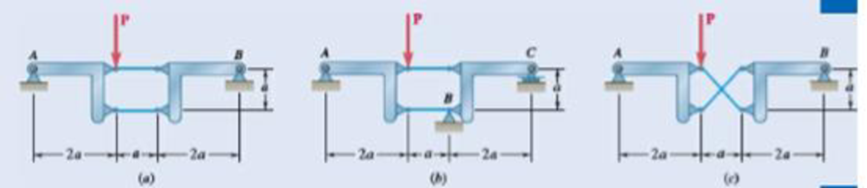
Fig. P6.121
The reactions at the frame and the rigidness of the frame.
Answer to Problem 6.121P
The reactions at the frame for figure (a) is
Explanation of Solution
The following figure gives the free body diagram of the first part of the member in figure P6.121(a).
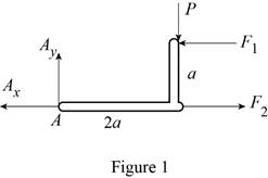
Write the equation to find the moment of force.
Here,
Write the equation to find the total moment about the point
Write the equations for equilibrium for the free body diagram in figure 1.
Here,
The following figure gives the free body diagram of the second part of the member in figure P6.121(a).
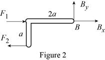
Write the equations for equilibrium for the free body diagram in figure 2.
Here,
The following figure gives the free body diagram of the first part of the member in figure P6.119(b).
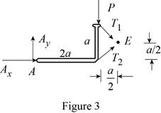
Write the equations for equilibrium for the free body diagram in figure 3.
Here,
The following figure gives the free body diagram of the second part of the member in figure P6.119(b).
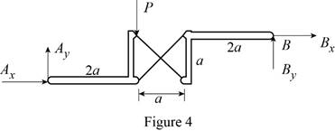
Write the equations for equilibrium for the free body diagram in figure 4.
Here,
The following figure gives the free body diagram of the member in figure P6.119(c).
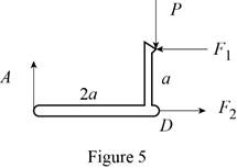
Write the equations for equilibrium for the free body diagram in figure 5.
Here,
The following figure gives the free body diagram of right part of the member in figure P6.119(c).
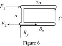
Write the equations for equilibrium for the free body diagram in figure 6.
Here,
Write the expression to find the magnitude of the vector from its components.
Here,
Write the equation to find the angle of orientation of the vector
Conclusion:
Solve equation (I) using figure 1.
Rewrite the above equation.
Solve equation (III) using figure 1.
Rewrite the above equation.
Solve equation (IV) using figure 2.
Rewrite the above equation.
Solve equation (V) using figure 2.
Substitute
Solve equation (VI) using figure 2.
Substitute
Rewrite equation (XIV) in terms of the vector
Substitute
Rewrite equation (XV) in terms of the vector
Substitute
Rewrite equation (XIV) in terms of the vector
Substitute
Solve equation (VII) using figure 3.
Rewrite the above equation.
Solve equation (VIII) using figure 4.
Rewrite the above equation.
Solve the conditions obtained from figure 3 and 4.
Solve equation (IX) using figure 5.
Rewrite the above equation to find
Solve equation (X) using figure 5.
Substitute
Solve equation (XI) using figure 5.
Substitute
Solve equation (XII) using figure 6.
Substitute
Solve equation (XII) to the right using figure 6.
Substitute
Solve equation (XII) upwards using figure 6.
Substitute
Therefore, the reactions at the frame for figure (a) is
Want to see more full solutions like this?
Chapter 6 Solutions
VECTOR MECH....F/ENGNRS-STATICS -CONNECT


- Procedure: 1- Cartesian system, 2D3D, type of support 2- Free body diagram 3 - Find the support reactions 4- If you find a negative number then flip the force 5- Find the internal force 3D ∑Fx=0 ∑Fy=0 ∑Fz=0 ∑Mx=0 ∑My=0 ΣMz=0 2D ΣFx=0 ΣFy=0 ΣMz=0 5- Use method of section and cut the element where you want to find the internal force and keep either side of thearrow_forwardProcedure:1- Cartesian system, 2D3D,type of support2- Free body diagram3 - Find the support reactions4- If you find a negativenumber then flip the force5- Find the internal force3D∑Fx=0∑Fy=0∑Fz=0∑Mx=0∑My=0\Sigma Mz=02D\Sigma Fx=0\Sigma Fy=0\Sigma Mz=05- Use method of sectionand cut the elementwhere you want to findthe internal force andkeep either side of thearrow_forwardProcedure: 1- Cartesian system, 2(D)/(3)D, type of support 2- Free body diagram 3 - Find the support reactions 4- If you find a negative number then flip the force 5- Find the internal force 3D \sum Fx=0 \sum Fy=0 \sum Fz=0 \sum Mx=0 \sum My=0 \Sigma Mz=0 2D \Sigma Fx=0 \Sigma Fy=0 \Sigma Mz=0 5- Use method of section and cut the element where you want to find the internal force and keep either side of the sectionarrow_forward
- Procedure: 1- Cartesian system, 2(D)/(3)D, type of support 2- Free body diagram 3 - Find the support reactions 4- If you find a negative number then flip the force 5- Find the internal force 3D \sum Fx=0 \sum Fy=0 \sum Fz=0 \sum Mx=0 \sum My=0 \Sigma Mz=0 2D \Sigma Fx=0 \Sigma Fy=0 \Sigma Mz=0 5- Use method of section and cut the element where you want to find the internal force and keep either side of the sectionarrow_forwardFor each system below with transfer function G(s), plot the pole(s) on the s-plane. and indicate whether the system is: (a) "stable" (i.e., a bounded input will always result in a bounded output), (b) "marginally stable," or (c) "unstable" Sketch a rough graph of the time response to a step input. 8 a) G(s) = 5-5 8 b) G(s) = c) G(s) = = s+5 3s + 8 s² - 2s +2 3s +8 d) G(s): = s²+2s+2 3s+8 e) G(s): = s² +9 f) G(s): 8 00 == Sarrow_forwardPlease answer the following question. Include all work and plase explain. Graphs are provided below. "Consider the Mg (Magnesium) - Ni (Nickel) phase diagram shown below. This phase diagram contains two eutectic reactions and two intermediate phases (Mg2Ni and MgNi2). At a temperature of 505oC, determine what the composition of an alloy would need to be to contain a mass fraction of 0.20 Mg and 0.80 Mg2Ni."arrow_forward
- The triangular plate, having a 90∘∘ angle at AA, supports the load PP = 370 lblb as shown in (Figure 1).arrow_forwardDesign a 4-bar linkage to carry the body in Figure 1 through the two positions P1 and P2 at the angles shown in the figure. Use analytical synthesis with the free choice values z = 1.075, q= 210°, ß2 = −27° for left side and s = 1.24, y= 74°, ½ = − 40° for right side. φ 1.236 P2 147.5° 210° 2.138 P1 Figure 1 Xarrow_forwardDesign a 4-bar linkage to carry the body in Figure 1 through the two positions P1 and P2 at the angles shown in the figure. Use analytical synthesis with the free choice values z = 1.075, q= 210°, B₂ = −27° for left side and s = 1.24, y= 74°, ½ = − 40° for right side. 1.236 P2 147.5° 210° P1 Figure 1 2.138 Xarrow_forward
- can you explain how in a coordinate frame transformation: v = {v_n}^T {n-hat} and then it was found that {n-hat} = [C]^T {b-hat} so v_n = {v_n}^T [C]^T {b-hat}, how does that equation go from that to this --> v_n = [C]^T v_barrow_forward6) If (k = 0,7 cm) find Imax for figure below. 225mm 100mm ثلاثاء. 100mm 150mm 75mm Ans: Tmax=45:27 N/cm F-400 Narrow_forwardThe man has a weight W and stands halfway along the beam. The beam is not smooth, but the planes at A and B are smooth (and plane A is horizontal). Determine the magnitude of the tension in the cord in terms of W and θ.arrow_forward
 Elements Of ElectromagneticsMechanical EngineeringISBN:9780190698614Author:Sadiku, Matthew N. O.Publisher:Oxford University Press
 Mechanics of Materials (10th Edition)Mechanical EngineeringISBN:9780134319650Author:Russell C. HibbelerPublisher:PEARSON
 Thermodynamics: An Engineering ApproachMechanical EngineeringISBN:9781259822674Author:Yunus A. Cengel Dr., Michael A. BolesPublisher:McGraw-Hill Education
 Control Systems EngineeringMechanical EngineeringISBN:9781118170519Author:Norman S. NisePublisher:WILEY
 Mechanics of Materials (MindTap Course List)Mechanical EngineeringISBN:9781337093347Author:Barry J. Goodno, James M. GerePublisher:Cengage Learning
 Engineering Mechanics: StaticsMechanical EngineeringISBN:9781118807330Author:James L. Meriam, L. G. Kraige, J. N. BoltonPublisher:WILEY