
Videos
(a)
The components of the forces exerted on member BCDF at C and D.
(a)
Answer to Problem 6.104P
The x component of force at D,
Explanation of Solution
Figure 1 is the free body diagram of the entire frame of the system.
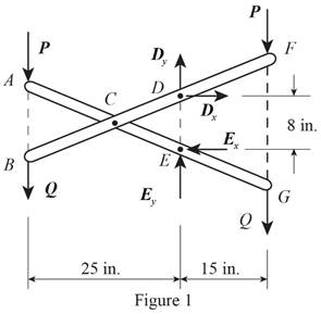
Write the equation to find the sum of the moments about point E.
Here,
Write the equation to find the sum of x components of force.
Here,
Consider the member BCDF of the system.
Figure 2 shown below is the free body diagram of member BCDF.
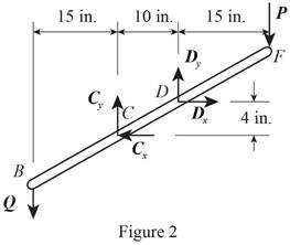
Write the equation to find the sum of x component of force.
Here,
Write the equation to find the sum of moments at D.
Here,
Write the equation to find the sum of y components of force.
Here,
Consider the free body diagram of member ACEG. The free body diagram of ACEG is given in figure 3.
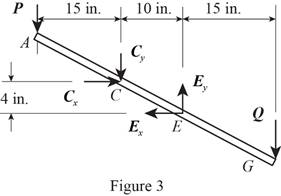
Write the equation to find the sum of y component of force.
Here,
Conclusion:
Solve equation (I) to get the value of
Substitute
Solve equation (III) to get the value of
Substitute
Substitute
 Substitute
Substitute
Substitute
Therefore, The x component of force at D,
(b)
The component of force on member ACEG at E.
(b)
Answer to Problem 6.104P
The x component of force at E,
Explanation of Solution
Rewrite equation (II) to find the x component of force at E.
Here,
Rewrite equation (VI) to get the y component of force at E.
Here,
Conclusion:
Substitute
Substitute
Substitute
Substitute

Therefore, The x component of force at E,
Want to see more full solutions like this?
Chapter 6 Solutions
VECTOR MECH....F/ENGNRS-STATICS -CONNECT


- 1. Calculation Calculate the DOF of the following mechanis m 2 3 1 Please enter the answerarrow_forwarda) Determine state of stress at all points (a, b and c). These points are located on the exteriorsurface of the beam. Point a is located along the centreline of the beam, point b is 15mmfrom the centreline and point c is located on the edge of the beam. Present yourresults in a table and ensure that your sign convention is clearly shownb) Construct Mohrs circle at this point andcalculate the principal stresses and maximum in‐plane shear stress (τmax) at pointc. sketch the resulting state of stress at this point clearly indicating themagnitude of the stresses and any angles associated with the state of stress (principal ormaximum in‐plane shear).arrow_forwardparts e,f,garrow_forward
- Figure 9-6 9-49 An aluminum alloy plate with dimensions 20 cm x 10 cm × 2 cm needs to be cast with a secondary dendrite arm spacing of 10-2 cm (refer to Figure 9-6). What mold constant B is required (assume n = 2 )? Secondary dendrite arm spacing (cm) - 10-1 10-2 10-3 10 41 0.1 1 Copper Zinc alloys Aluminum alloys 10 100 1,000 10,000 100,000 Solidification time (s)arrow_forward9-72 Figure 9-29 shows a cylindrical riser attached to a casting. Compare the solidification times for each casting section and the riser and determine whether the riser will be effective. Figure 9-29 Т 3 6 3 8 3 6 Details A diagram shows the step-block casting. A cylinder of height "7" and diameter "3" is kept on a platform consisting of 2 steps. The width of the second step of the platform is labeled as "3". The horizontal length of the first step is labeled as "6." The horizontal length, width and height of the first step are labeled "6", "8" and "3".arrow_forward6/94 Determine the minimum coefficient of static friction for which the bar can be in static equilibrium in the config- uration shown. The bar is uniform and the fixed peg at C is small. Neglect friction at B. A L PROBLEM 6/94 B L 22arrow_forward
 International Edition---engineering Mechanics: St...Mechanical EngineeringISBN:9781305501607Author:Andrew Pytel And Jaan KiusalaasPublisher:CENGAGE L