
Concept explainers
Videos
The truss shown consists of nine members and is support by a ball-and-socket at B, a short link at C, and two short links at D. (a) Check that this truss is a simple truss, that completely constrained, and that the reactions at its suppo are statically determinate. (b) Determine the force in each member for P = (−1200 N)j and Q = 0.
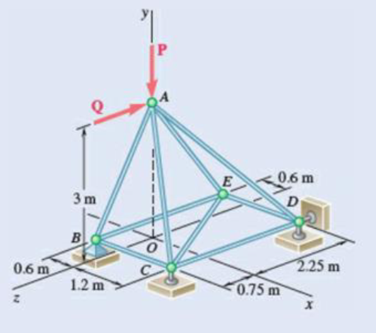
Fig. P6.39
(a)
Verify that the truss is a simple truss, completely constrained, and the reactions at the supports are statically determinate.
Answer to Problem 6.39P
The reactions at supports B, C, and D is
Explanation of Solution
Given information:
The value of the force P is
The value of the force Q is zero.
Calculation:
Show the free-body diagram of the truss as in Figure 1.
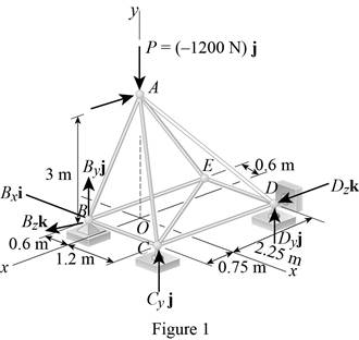
Find the vector coordinates by taking moment about point B.
Equate the coefficients of i to zero.
Equate the coefficients of j to zero.
Equate the coefficients of k to zero.
Substitute 300 N for
Resolve the force components in y-axis.
Substitute 300 N for
The unknown reactions can be calculated with the equilibrium equations. Therefore, the truss is statically determinate, completely constrained and simple truss.
Thus, the reactions at supports B, C, and D is
(b)
Find the force in each member of the truss.
Answer to Problem 6.39P
The force in the member AB is
The force in the member BC is
The force in the member BE is
The force in the member AC is
The force in the member CE is
The force in the member CD is
The force in the member AD is
The force in the member DE is
The force in the member AE is
Explanation of Solution
Show the free-body diagram of the joint B as in Figure 2.
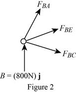
Resolve the force components as follows;
Write the vector value of
Find the scalar quantity of BA using the relation.
Find the force in the member AB as follows;
Substitute
Find the force in the member BC as follows;
Find the force in the member BE as follows;
Equate the coefficients of j to zero.
Equate the coefficients of i to zero.
Substitute –840 N for
Equate the coefficients of k to zero.
Substitute –840 N for
Therefore,
The force in the member AB is
The force in the member BC is
The force in the member BE is
Show the free-body diagram of the joint C as in Figure 3.
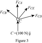
Resolve the force components as follows;
Write the vector value of
Find the scalar quantity of CA using the relation.
Find the force in the member AC as follows;
Substitute
Find the force in the member CB as follows;
Find the force in the member CD as follows;
Write the vector value of
Find the scalar quantity of CE using the relation.
Find the force in the member CE as follows;
Substitute
Equate the coefficients of j to zero.
Equate the coefficients of i to zero.
Substitute –110.6 N for
Equate the coefficients of k to zero.
Substitute –110.6 N for
Therefore,
The force in the member AC is
The force in the member CE is
The force in the member CD is
Show the free-body diagram of the joint D as in Figure 4.
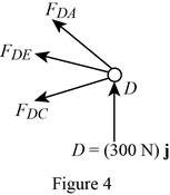
Resolve the force components as follows;
Write the vector value of
Find the scalar quantity of DA using the relation.
Find the force in the member AD as follows;
Substitute
Find the force in the member DC as follows;
Find the force in the member DE as follows;
Equate the coefficients of j to zero.
Equate the coefficients of i to zero.
Substitute –394 N for
Therefore,
The force in the member AD is
The force in the member DE is
Show the free-body diagram of the joint E as in figure 5.
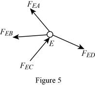
The member AE is not in the xz plane.
Therefore, the force in the member AE is
Want to see more full solutions like this?
Chapter 6 Solutions
Vector Mechanics for Engineers: Statics


- 1. The shaft AD in Figure 1 supports two pulleys at B and C of radius 200 mm and 250 mm respectively. The shaft is supported in frictionless bearings at A and D and is rotating clockwise (when viewed from the right) at a constant speed of 300 rpm. Only bearing A can support thrust. The tensions T₁ = 200 N, T₂ = 400 N, and T3 = 300 N. The distances AB = 120 mm, BC = 150 mm, and CD120 mm. Find the tension 74 and the reaction forces at the bearings. A T fo Figure 1arrow_forward5. Figure 5 shows a two-dimensional idealization of the front suspension system for a car. During cornering, the road exerts a vertical force of 5 kN and a leftward horizontal force of 1.2 kN on the tire, which is of 510 mm diameter. Draw free-body diagrams of each component and determine the forces transmitted between them. 250 A -320 B 170 D 170 -220-220- all dimensions in mm. Figure 5arrow_forward8. The force F in Figure 8 is 120 lb and the angle 0 = 25°. Find the axial force N, the shear force V and the bending moment M at the point K which is midway between B and C and illustrate their directions on a sketch of the segment KCD. E -0 B K అ D H 7 A- all dimensions in inches Figure 8 Ꮎ G Farrow_forward
- 6. Determine the coordinates x, y of the centroid of the area shaded in Figure 6. y y=x³ Figure 6 3arrow_forward3. Use the method of sections to determine the forces in the members BD, CD, CE in the struc- ture of Figure 3. A B D 4 kN 6 kN all dimensions in meters. Figure 3arrow_forwardA pipeline engineer is considering alternative natural gas pipeline routings. The first route is mostly over land and the second is primarily undersea. Both pipelines will need some valve and fitting replacements in year 25. Cost data for each route is shown in Table P2.21. Notice that the undersea route has a higher initial cost due to higher installation costs and extra corrosion protection for the pipeline. However, the undersea route has cheaper security and maintenance costs which substantially reduces annual costs. The MARR for the project is 15%. Determine which route should be pursued based on a present worth analysis.arrow_forward
- The state of stress at a point is σ = -4.00 kpsi, σy Tyz = 8.000 kpsi, and T₂ = -14.00 kpsi. What is the maximum shear stress for this case? The maximum shear stress is kpsi. = 16.00 kpsi, σ = -14.00 kpsi, Try = 11.00 kpsi,arrow_forwardThe initial cost of a proposed heat recovery system is $375,000. The annual operation andmaintenance costs are projected to be $12,000. The salvage value of the system at the end of itsuseful life (projected to be 30 years) is $60,000. The annual savings in fuel costs resulting fromthis system are estimated to be $55,000 per year.a. Assuming annual compounding, determine the rate of return for this heat recovery system.b. If management has set the MARR to be 15% for a heat recovery system like this, what is themaximum initial cost that can be spent on the system (assuming that all other costs and incomesare the same)?arrow_forwardThe initial cost of a machine for a production facility is $225,000. The machine is expected tolast for 10 years with no salvage value. The company’s tax rate is 49% and SLD is used todepreciate the machine. For this type of depreciation, the tax life of the machine is considered 8years and its salvage value is $5,000. The after-tax rate of return is 14.3%. Determine the uniformannual before-tax cash flow.arrow_forward
- Three alternatives are being considered for an air cleaning system. All three systems have a lifeof 10 years with no salvage value. System A has an initial cost of $29,000. During the first fiveyears of operation, the annual costs to operate system A are $5,000. During the second five years,the annual cost of system A increases to $16,000. System B has an initial cost of $43,000. Theannual cost to operate system B is $4,000, however, after the first year, this cost increases by$1,600 per year. System C has an initial cost of $58,000 with an annual cost of $2,400. System Crequires two upgrades: one during year 4 which costs $6,000, and the other during year 8 whichcosts $3,000. The MARR for this project is 17%. Determine which air cleaning system should beinstalled based on an economic analysis.arrow_forwardShow all work as much as you can and box out answersarrow_forwardShow as much work as possible and box out answers pleasearrow_forward
 International Edition---engineering Mechanics: St...Mechanical EngineeringISBN:9781305501607Author:Andrew Pytel And Jaan KiusalaasPublisher:CENGAGE L