
Concept explainers
Videos
The force in each of the members of the truss for the given loading.
Answer to Problem 6.38P
The force in member
Explanation of Solution
The free-body diagram of the entire truss is shown in figure 1.
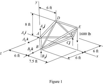
Refer to figure 1 and use symmetry.
Here,
The
Here,
Sum of the moments must be equal to zero.
Here,
Write the equation for
Here,
Put the above equation in equation (I).
Write the expression for the reaction at the point A.
Here,
Substitute
Use symmetry.
Here,
The
Here,
Write the expression for
Put the above equation in equation (II).
Write the expression for the reaction at the point A.
Here,
Substitute
Consider the free body
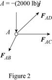
The net force must be equal to zero.
Here,
Write the expression for
Put the above equation in equation (III).
Here,
Write the expression for
Here,
Write the expression for
Here,
Write the expression for
Here,
Put equations (V), (VI) and (VII) in equation (IV).
Factorize
Equate the coefficient of
Equate the coefficient of
Equate the coefficient of
Put equation (X) in equation (IX).
Substitute
Put the above equation in equation (X).
Consider the free-body joint B. The free-body diagram of joint B is shown in figure 3.
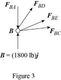
Refer to figure (3) and write the expression for the forces.
Here,
Substitute
Write the expression for
Here,
Write the expression for
Here,
Write the expression for
Here,
Substitute
Write the expression for
Put the above equation in equation (III).
Put equations (XI), (XII), (XIII) , (XIV) and substitute
Equate the coefficient of
Equate the coefficient of
Substitute
Equate the coefficient of
Substitute
Use symmetry.
Here,
Substitute
Consider the free body joint D. The free body diagram is shown in figure 4.
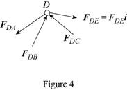
Write the expression for
Put the above equation in equation (III).
Only
Equate the coefficient of
Substitute
Conclusion:
Thus, the force in member
Want to see more full solutions like this?
Chapter 6 Solutions
Vector Mechanics for Engineers: Statics


- A mass of ideal gas in a closed piston-cylinder system expands from 427 °C and 16 bar following the process law, pv1.36 = Constant (p times v to the power of 1.36 equals to a constant). For the gas, initial : final pressure ratio is 4:1 and the initial gas volume is 0.14 m³. The specific heat of the gas at constant pressure, Cp = 0.987 kJ/kg-K and the specific gas constant, R = 0.267 kJ/kg.K. Determine the change in total internal energy in the gas during the expansion. Enter your numerical answer in the answer box below in KILO JOULES (not in Joules) but do not enter the units. (There is no expected number of decimal points or significant figures).arrow_forwardmy ID# 016948724. Please solve this problem step by steparrow_forwardMy ID# 016948724 please find the forces for Fx=0: fy=0: fz=0: please help me to solve this problem step by steparrow_forward
- My ID# 016948724 please solve the proble step by step find the forces fx=o: fy=0; fz=0; and find shear moment and the bending moment diagran please draw the diagram for the shear and bending momentarrow_forwardMy ID#016948724. Please help me to find the moment of inertia lx ly are a please show to solve step by stepsarrow_forwardplease solve this problem step by steparrow_forward
- Please do not use any AI tools to solve this question. I need a fully manual, step-by-step solution with clear explanations, as if it were done by a human tutor. No AI-generated responses, please.arrow_forwardPlease do not use any AI tools to solve this question. I need a fully manual, step-by-step solution with clear explanations, as if it were done by a human tutor. No AI-generated responses, please.arrow_forwardPlease do not use any AI tools to solve this question. I need a fully manual, step-by-step solution with clear explanations, as if it were done by a human tutor. No AI-generated responses, please.arrow_forward
 International Edition---engineering Mechanics: St...Mechanical EngineeringISBN:9781305501607Author:Andrew Pytel And Jaan KiusalaasPublisher:CENGAGE L