
Videos
(a)
The components of the forces exerted on member BCDF at C and D.
(a)
Answer to Problem 6.103P
The x component of force at D,
Explanation of Solution
Figure 1 is the free body diagram of the entire frame of the system.
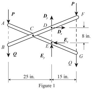
Write the equation to find the sum of the moments about point E.
Here,
Write the equation to find the sum of x components of force.
Here,
Consider the member BCDF of the system.
Figure 2 shown below is the free body diagram of member BCDF.
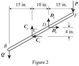
Write the equation to find the sum of x component of force.
Here,
Write the equation to find the sum of moments at D.
Here,
Write the equation to find the sum of y components of force.
Here,
Consider the free body diagram of member ACEG. The free body diagram of ACEG is given in figure 3.
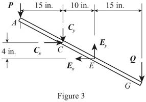
Write the equation to find the sum of y component of force.
Here,
Conclusion:
Solve equation (I) to get the value of
Substitute
Solve equation (III) to get the value of
Substitute
Substitute
 Substitute
Substitute
Substitute
Therefore, The x component of force at D,
(b)
The component of force on member ACEG at E.
(b)
Answer to Problem 6.103P
The x component of force at E,
Explanation of Solution
Rewrite equation (II) to find the x component of force at E.
Here,
Rewrite equation (VI) to get the y component of force at E.
Here,
Conclusion:
Substitute
Substitute
Substitute
Substitute
Therefore, The x component of force at E,
Want to see more full solutions like this?
Chapter 6 Solutions
Vector Mechanics for Engineers: Statics


- Required information An eccentric force P is applied as shown to a steel bar of 25 × 90-mm cross section. The strains at A and B have been measured and found to be εΑ = +490 μ εB=-70 μ Know that E = 200 GPa. 25 mm 30 mm 90 mm 45 mm B Determine the distance d. The distance dis 15 mm mm.arrow_forwardhandwritten-solutions, please!arrow_forwardhandwritten-solutions, please!arrow_forward
- ! Required information Assume that the couple shown acts in a vertical plane. Take M = 25 kip.in. r = 0.75 in. A B 4.8 in. M 1.2 in. [1.2 in. Determine the stress at point B. The stress at point B is ksi.arrow_forwardhandwritten-solutions, please!arrow_forwardhandwritten-solutions, please!arrow_forward
- No use chatgptarrow_forwardProblem 6 (Optional, extra 6 points) 150 mm 150 mm 120 mm 80 mm 60 mm PROBLEM 18.103 A 2.5 kg homogeneous disk of radius 80 mm rotates with an angular velocity ₁ with respect to arm ABC, which is welded to a shaft DCE rotating as shown at the constant rate w212 rad/s. Friction in the bearing at A causes ₁ to decrease at the rate of 15 rad/s². Determine the dynamic reactions at D and E at a time when ₁ has decreased to 50 rad/s. Answer: 5=-22.01 +26.8} N E=-21.2-5.20Ĵ Narrow_forwardProblem 1. Two uniform rods AB and CE, each of weight 3 lb and length 2 ft, are welded to each other at their midpoints. Knowing that this assembly has an angular velocity of constant magnitude c = 12 rad/s, determine: (1). the magnitude and direction of the angular momentum HD of the assembly about D. (2). the dynamic reactions (ignore mg) at the bearings at A and B. 9 in. 3 in. 03 9 in. 3 in. Answers: HD = 0.162 i +0.184 j slug-ft²/s HG = 2.21 k Ay =-1.1 lb; Az = 0; By = 1.1 lb; B₂ = 0.arrow_forward
- Problem 5 (Optional, extra 6 points) A 6-lb homogeneous disk of radius 3 in. spins as shown at the constant rate w₁ = 60 rad/s. The disk is supported by the fork-ended rod AB, which is welded to the vertical shaft CBD. The system is at rest when a couple Mo= (0.25ft-lb)j is applied to the shaft for 2 s and then removed. Determine the dynamic reactions at C and D before and after the couple has been removed at 2 s. 4 in. C B Mo 5 in 4 in. Note: 2 rotating around CD induced by Mo is NOT constant before Mo is removed. and ₂ (two unknowns) are related by the equation: ₂ =0+ w₂t 3 in. Partial Answer (after Mo has been removed): C-7.81+7.43k lb D -7.81 7.43 lbarrow_forwardProblem 4. A homogeneous disk with radius and mass m is mounted on an axle OG with length L and a negligible mass. The axle is pivoted at the fixed-point O, and the disk is constrained to roll on a horizontal surface. The disk rotates counterclockwise at the constant rate o₁ about the axle. (mg must be included into your calculation) (a). Calculate the linear velocity of G and indicate it on the figure. (b). Calculate ₂ (constant), which is the angular velocity of the axle OG around the vertical axis. (c). Calculate the linear acceleration ā of G and indicate it on the figure. (d). Determine the force (assumed vertical) exerted by the floor on the disk (e). Determine the reaction at the pivot O. 1 Answers: N = mg +mr(r/L)² @² |j mr w IIG C R L i+ 2L =arrow_forwardProblem 2. The homogeneous disk of weight W = 6 lb rotates at the constant rate co₁ = 16 rad/s with respect to arm ABC, which is welded to a shaft DCE rotating at the constant rate 2 = 8 rad/s. Assume the rod weight is negligible compared to the disk. Determine the dynamic reactions at D and E (ignore mg). Answers: D=-7.12ĵ+4.47k lb r-8 in. 9 in. B D E=-1.822+4.47 lb 9 in. E 12 in. 12 in. xarrow_forward
 International Edition---engineering Mechanics: St...Mechanical EngineeringISBN:9781305501607Author:Andrew Pytel And Jaan KiusalaasPublisher:CENGAGE L