
VECTOR MECH. FOR EGR: STATS & DYNAM (LL
12th Edition
ISBN: 9781260663778
Author: BEER
Publisher: MCG
expand_more
expand_more
format_list_bulleted
Concept explainers
Videos
Textbook Question
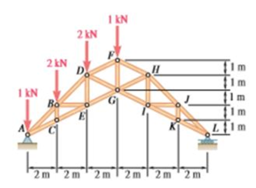
Chapter 6.1, Problem 6.21P
Determine the force in each of the members located to the left of FG for the scissors roof truss shown. State whether each member is in tension or compression.
Expert Solution & Answer
Want to see the full answer?
Check out a sample textbook solution
Students have asked these similar questions
a problem existed at the stocking stations of a mini-load AS/RS (automated storage and retrieval system) of a leading electronics manufacturer (Fig.1). At these stations, operators fill the bin delivered by the crane with material arriving in a tote over a roller conveyor. The conveyor was designed at such a height that it was impossible to reach the hooks comfortably even with the tote extended. Furthermore, cost consideration came into the picture and the conveyor height was not reduced. Instead, a step stool was considered to enable the stocker to reach the moving hooks comfortably. The height of the hooks from the floor is 280.2 cm (AD). The tote length is 54.9 cm. The projection of tote length and arm reach, CB = 66.1 cm. a) What anthropometric design principles would you follow to respectively calculate height, length, and width of the step to make it usable to a large number of people? b) What is the minimum height (EF) of the step with no shoe allowance? c) What is the minimum…
Qu. 5 Composite materials are becoming more widely used in aircraft industry due to their high strength, low weight and excellent corrosion resistant properties. As an engineer who is given task to design the I beam section of an aircraft (see Figure 7) please, answer the following questions given the material properties in Table 3.
Determine the Moduli of Elasticity of Carbon/Epoxy, Aramid/Epoxy, and Boron /Epoxy composites in the longitudinal direction, given that the composites consist of 25 vol% epoxy and 75 vol% fiber.
What are the specific moduli of each of these composites?
What are the specific strengths (i.e. specific UTS) of each of these composites?
What is the final cost of each of these composites?please show all work step by step problems make sure to see formula material science
Mueh
Battery operated train
Coll
160,000kg 0.0005 0.15 5m² 1.2kg/m³
CD
Af Pair
19
пре neng
0.98 0.9
0.88
Tesla Prated
Tesla Trated "wheel ng
Joxle
270 kW
440NM
0,45m 20
8.5kg m2
the middle
Consider a drive cycle of a 500km trip with 3 stops in
Other than the acceleration and deceleration
associated with the three stops, the tran maintains
constat cruise speed velocity of 324 km/hr. The
tran will fast charge at each stop for 15 min at a
rate Peharge = 350 kW
ΟΙ
15MIN
Stop
w charging
(350kW)
(ผม
τ
(AN
GMIJ
t
6M
1) HOW MUCH DISTANCE dace is covered DURING THE
ACCELERATION TO 324 km/hr?
2)
DETERMINE HOW LONG (IN seconds) the tran will
BE TRAVELING AT FULL SPEED
2
?
3) CALCULATE THE NET ENERGY GAW PER STOP
ete
Chapter 6 Solutions
VECTOR MECH. FOR EGR: STATS & DYNAM (LL
Ch. 6.1 - Using the method of joints, determine the force in...Ch. 6.1 - Using the method of joints, determine the force in...Ch. 6.1 - Using the method of joints, determine the force in...Ch. 6.1 - Using the method of joints, determine the force in...Ch. 6.1 - Using the method of joints, determine the force in...Ch. 6.1 - Using the method of joints, determine the force in...Ch. 6.1 - Using the method of joints, determine the force in...Ch. 6.1 - Using the method of joints, determine the force in...Ch. 6.1 - Using the method of joints, determine the force in...Ch. 6.1 - Determine the force in each member of the truss...
Ch. 6.1 - Determine the force in each member of the Gambrel...Ch. 6.1 - Determine the force in each member of the Howe...Ch. 6.1 - Using the method of joints, determine the force in...Ch. 6.1 - Using the method of joints, determine the force in...Ch. 6.1 - Determine the force in each member of the Warren...Ch. 6.1 - Solve Problem 6.15 assuming that the load applied...Ch. 6.1 - Determine the force in each member of the Pratt...Ch. 6.1 - The truss shown is one of several supporting an...Ch. 6.1 - Determine the force in each member of the Pratt...Ch. 6.1 - Prob. 6.20PCh. 6.1 - Determine the force in each of the members located...Ch. 6.1 - Determine the force in member DE and in each of...Ch. 6.1 - Determine the force in each of the members located...Ch. 6.1 - The portion of truss shown represents the upper...Ch. 6.1 - For the tower and loading of Prob. 6.24 and...Ch. 6.1 - Solve Problem 6.24 assuming that the cables...Ch. 6.1 - Determine the force in each member of the truss...Ch. 6.1 - Determine the force in each member of the truss...Ch. 6.1 - Determine whether the trusses of Problems 6.31a,...Ch. 6.1 - Determine whether the trusses of Problems 6.31b,...Ch. 6.1 - For the given loading, determine the zero-force...Ch. 6.1 - Prob. 6.32PCh. 6.1 - For the given loading, determine the zero-force...Ch. 6.1 - Prob. 6.34PCh. 6.1 - Prob. 6.35PCh. 6.1 - Prob. 6.36PCh. 6.1 - The truss shown consists of six members and is...Ch. 6.1 - The truss shown consists of nine members and is...Ch. 6.1 - The truss shown consists of nine members and is...Ch. 6.1 - Solve Prob. 6.39 for P = 0 and Q = (900 N)k. 6.39...Ch. 6.1 - The truss shown consists of 18 members and is...Ch. 6.1 - The truss shown consists of 18 members and is...Ch. 6.2 - Determine the force in members BD and DE of the...Ch. 6.2 - Determine the force in members DG and EG of the...Ch. 6.2 - Determine the force in members BD and CD of the...Ch. 6.2 - Determine the force in members DF and DG of the...Ch. 6.2 - A floor truss is loaded as shown. Determine the...Ch. 6.2 - A floor truss is loaded as shown. Determine the...Ch. 6.2 - Determine the force in members CD and DF of the...Ch. 6.2 - Determine the force in members CE and EF of the...Ch. 6.2 - Determine the force in members DE and DF of the...Ch. 6.2 - Prob. 6.52PCh. 6.2 - Determine the force in members DF and DE of the...Ch. 6.2 - Prob. 6.54PCh. 6.2 - A Pratt roof truss is loaded as shown. Determine...Ch. 6.2 - A Pratt roof truss is loaded as shown. Determine...Ch. 6.2 - A Howe scissors roof truss is loaded as shown....Ch. 6.2 - A Howe scissors roof truss is loaded as shown....Ch. 6.2 - Determine the force in members AD, CD, and CE of...Ch. 6.2 - Determine the force in members DG, FG, and FH of...Ch. 6.2 - Determine the force in member GJ of the truss...Ch. 6.2 - Determine the force in members DG and FH of the...Ch. 6.2 - Determine the force in members CD and JK of the...Ch. 6.2 - Determine the force in members DE and KL of the...Ch. 6.2 - The diagonal members in the center panels of the...Ch. 6.2 - The diagonal members in the center panels of the...Ch. 6.2 - Prob. 6.67PCh. 6.2 - Prob. 6.68PCh. 6.2 - Classify each of the structures shown as...Ch. 6.2 - Classify each of the structures shown as...Ch. 6.2 - Prob. 6.71PCh. 6.2 - 6.70 through 6.74 classify as determinate or...Ch. 6.2 - 6.70 through 6.74 classify as determinate or...Ch. 6.2 - 6.70 through 6.74 classify as determinate or...Ch. 6.3 - For the frame and loading shown, draw the...Ch. 6.3 - For the frame and loading shown, draw the...Ch. 6.3 - Draw the free-body diagram(s) needed to determine...Ch. 6.3 - Knowing that the pulley has a radius of 0.5 m,...Ch. 6.3 - and 6.76 Determine the force in member BD and the...Ch. 6.3 - and 6.76 Determine the force in member BD and the...Ch. 6.3 - For the frame and loading shown, determine the...Ch. 6.3 - Determine the components of all forces acting on...Ch. 6.3 - The hydraulic cylinder CF, which partially...Ch. 6.3 - The hydraulic cylinder CF, which partially...Ch. 6.3 - Determine the components of all forces acting on...Ch. 6.3 - Determine the components of all forces acting on...Ch. 6.3 - Determine the components of the reactions at A and...Ch. 6.3 - Determine the components of the reactions at D and...Ch. 6.3 - Determine the components of the reactions at A and...Ch. 6.3 - Determine the components of the reactions at A and...Ch. 6.3 - Prob. 6.87PCh. 6.3 - The 48-lb load can be moved along the line of...Ch. 6.3 - The 48-lb load is removed and a 288-lb in....Ch. 6.3 - (a) Show that, when a frame supports a pulley at...Ch. 6.3 - Knowing that each pulley has a radius of 250 mm,...Ch. 6.3 - Knowing that the pulley has a radius of 75 mm,...Ch. 6.3 - Two 9-in.-diameter pipes (pipe 1 and pipe 2) are...Ch. 6.3 - Prob. 6.94PCh. 6.3 - Prob. 6.95PCh. 6.3 - Prob. 6.96PCh. 6.3 - Prob. 6.97PCh. 6.3 - Prob. 6.98PCh. 6.3 - Knowing that P = 90 lb and Q = 60 lb, determine...Ch. 6.3 - Knowing that P = 90 lb and Q = 60 lb, determine...Ch. 6.3 - For the frame and loading shown, determine the...Ch. 6.3 - For the frame and loading shown, determine the...Ch. 6.3 - Knowing that P = 15 lb and Q = 65 lb, determine...Ch. 6.3 - Knowing that P = 25 lb and Q = 55 lb, determine...Ch. 6.3 - For the frame and loading shown, determine the...Ch. 6.3 - Prob. 6.106PCh. 6.3 - The axis of the three-hinge arch ABC is a parabola...Ch. 6.3 - The axis of the three-hinge arch ABC is a parabola...Ch. 6.3 - Prob. 6.109PCh. 6.3 - Prob. 6.110PCh. 6.3 - 6.111, 6.112, and 6.113 Members ABC and CDE are...Ch. 6.3 - Prob. 6.112PCh. 6.3 - 6.111, 6.112, and 6.113 Members ABC and CDE are...Ch. 6.3 - Members ABC and CDE are pin-connected at C and...Ch. 6.3 - Solve Prob. 6.112 assuming that the force P is...Ch. 6.3 - Solve Prob. 6.114 assuming that the force P is...Ch. 6.3 - Prob. 6.117PCh. 6.3 - Prob. 6.118PCh. 6.3 - 6.119 through 6.121 Each of the frames shown...Ch. 6.3 - 6.119 through 6.121 Each of the frames shown...Ch. 6.3 - 6.119 through 6.121 Each of the frames shown...Ch. 6.4 - An 84-lb force is applied to the toggle vise at C....Ch. 6.4 - For the system and loading shown, draw the...Ch. 6.4 - Prob. 6.7FBPCh. 6.4 - The position of member ABC is controlled by the...Ch. 6.4 - The shear shown is used to cut and trim...Ch. 6.4 - A 100-lb force directed vertically downward is...Ch. 6.4 - Prob. 6.124PCh. 6.4 - The control rod CE passes through a horizontal...Ch. 6.4 - Solve Prob. 6.125 when (a) = 0, (b) = 6. Fig....Ch. 6.4 - The press shown is used to emboss a small seal at...Ch. 6.4 - The press shown is used to emboss a small seal at...Ch. 6.4 - Prob. 6.129PCh. 6.4 - The pin at B is attached to member ABC and can...Ch. 6.4 - Arm ABC is connected by pins to a collar at B and...Ch. 6.4 - Arm ABC is connected by pins to a collar at B and...Ch. 6.4 - The Whitworth mechanism shown is used to produce a...Ch. 6.4 - Prob. 6.134PCh. 6.4 - and 6.136 Two rods are connected by a slider block...Ch. 6.4 - and 6.136 Two rods are connected by a slider block...Ch. 6.4 - 6.137 and 6.138 Rod CD is attached to the collar D...Ch. 6.4 - 6.137 and 6.138 Rod CD is attached to the collar D...Ch. 6.4 - Two hydraulic cylinders control the position of...Ch. 6.4 - Prob. 6.140PCh. 6.4 - A steel ingot weighing 8000 lb is lifted by a pair...Ch. 6.4 - If the toggle shown is added to the tongs of Prob....Ch. 6.4 - A 9-m length of railroad rail of mass 40 kg/m is...Ch. 6.4 - Prob. 6.144PCh. 6.4 - The pliers shown are used to grip a...Ch. 6.4 - Prob. 6.146PCh. 6.4 - In using the bolt cutter shown, a worker applies...Ch. 6.4 - The upper blade and lower handle of the...Ch. 6.4 - Prob. 6.149PCh. 6.4 - and 6.150 Determine the force P that must be...Ch. 6.4 - Prob. 6.151PCh. 6.4 - Prob. 6.152PCh. 6.4 - The elevation of the platform is controlled by two...Ch. 6.4 - For the frame and loading shown, determine the...Ch. 6.4 - The telescoping arm ABC is used to provide an...Ch. 6.4 - The telescoping arm ABC of Prob. 6.155 can be...Ch. 6.4 - The motion of the backhoe bucket shown is...Ch. 6.4 - Prob. 6.158PCh. 6.4 - The gears A and D are rigidly attached to...Ch. 6.4 - In the planetary gear system shown, the radius of...Ch. 6.4 - Two shafts AC and CF, which lie in the vertical xy...Ch. 6.4 - Two shafts AC and CF, which lie in the vertical xy...Ch. 6.4 - The large mechanical tongs shown are used to grab...Ch. 6 - Using the method of joints, determine the force in...Ch. 6 - Using the method of joints, determine the force in...Ch. 6 - A stadium roof truss is loaded as shown. Determine...Ch. 6 - A stadium roof truss is loaded as shown. Determine...Ch. 6 - Determine the components of all forces acting on...Ch. 6 - Prob. 6.169RPCh. 6 - Knowing that the pulley has a radius of 50 mm,...Ch. 6 - For the frame and loading shown, determine the...Ch. 6 - For the frame and loading shown, determine the...Ch. 6 - Water pressure in the supply system exerts a...Ch. 6 - A couple M with a magnitude of 1.5 kNm is applied...Ch. 6 - Prob. 6.175RP
Knowledge Booster


Learn more about
Need a deep-dive on the concept behind this application? Look no further. Learn more about this topic, mechanical-engineering and related others by exploring similar questions and additional content below.Similar questions
- Please stop screenshoting ai solution,it always in accurate solve normalarrow_forwardResearch and select any different values for the Ratio of connecting rod length to crank radius from various engine models, then analyze how these changes affect instantaneous velocity and acceleration, presenting your findings visually using graphs.arrow_forwardPb 9) 4.44 bas gnibus& WX 002 grillimatul fred bail (e) For the simply supported I-beam, a load of 1000 lb in center. Find the maximum transverse shear stress. Compare your answer with the approximation obtained by dividing the shear load by the area of the web only with the web considered to extend for the full 8-in depth. - 3½ in. 12 bas in 0% to tolerabib tormi no grived in. 8 in. 38 in. 12 ½ in.arrow_forward
- Pb 12) 4.61 Draw the Mohr circle for the stresses experienced by the surface of an internally pressurized steel tube that is subject to the tangential and axial stresses in the outer surface of 45 ksi and 30 ksi, respectively, and a torsional stress of 18 ksi. yx 18 45 30arrow_forwardPb 8) 4.39 For the C-clamp shown, what force F can be exerted by the screw if the maximum tensile stress in the clamp is to be limited to 30 ksi? F 2 in. სის 3436 16 13 blos 0101 alos12 nodus 121A (s 3 in. in. 16 in. 16 web leonas OFF elson yollA (d 016 (& d of bolow-bloo ai 15912 020112LA sue) vilisub 22 bal.90 Swman a bris ctxibasqqA) laste is tools?arrow_forwardQuiz/An eccentrically loaded bracket is welded to the support as shown in Figure below. The load is static. The weld size for weld w1 is h1 = 6mm, for w2 h2 = 5mm, and for w3 is h3 =5.5 mm. Determine the safety factor (S.f) for the welds. F=22 kN. Use an AWS Electrode type (E90xx). 140 S Find the centroid I want university professor solutions O REDMI NOTE 8 PRO CAI QUAD CAMERA 101.15 Farrow_forward
- Pb 6) 4.31 do = 25 mm 4.31 What bending moment is required to produce a maximum normal stress of 400 MPa: (a) In a straight round rod of 40-mm diameter? (b) In a straight square rod, 40 mm on a side (with bending about the X axis as shown for a rectangular section in Appendix B-2)?arrow_forwardPb 13) 4.73 Find the maximum value of stress at the hole and semicircular notch. 45000 N 50 mm 100 mm 15 mm 25 mm 45000 Narrow_forwardPb 11) 4.53 Consider the 1-in solid round shaft supported by self-aligning bearings at A and B. Attached to the shaft are two chain sprockets that are loaded as shown. Treat this as a static loading problem and identify the specific shat location subjected to the most severe state of stress and make a Mohr circle representation of this stress state. 1-in.-dia. shaft 500 lb 2 in. 1000 lb 3 in. 3 in.arrow_forward
- Pb 5) 4.19 Estimate the torque required to produce a maximum shear stress of 570 MPa in a hollow shaft having an inner diameter of 20 mm and an outer diameter of 25 mm. d; = 20 mm T d = 25 mm Tmax = 570 MPaarrow_forwardQuiz/An eccentrically loaded bracket is welded to the support as shown in Figure below. The load is static. The weld size for weld w1 is h1 = 6mm, for w2 h2 = 5mm, and for w3 is h3 =5.5 mm. Determine the safety factor (S.f) for the welds. F=22 kN. Use an AWS Electrode type (E90xx). I want university professor solutions O REDMI NOTE 8 PRO CAI QUAD CAMERA 140 S 101.15 Farrow_forwardResearch and select different values for the R ratio from various engine models, then analyze how these changes affect instantaneous velocity and acceleration, presenting your findings visually using graphsarrow_forward
arrow_back_ios
SEE MORE QUESTIONS
arrow_forward_ios
Recommended textbooks for you
 Elements Of ElectromagneticsMechanical EngineeringISBN:9780190698614Author:Sadiku, Matthew N. O.Publisher:Oxford University Press
 Mechanics of Materials (10th Edition)Mechanical EngineeringISBN:9780134319650Author:Russell C. HibbelerPublisher:PEARSON
 Thermodynamics: An Engineering ApproachMechanical EngineeringISBN:9781259822674Author:Yunus A. Cengel Dr., Michael A. BolesPublisher:McGraw-Hill Education
 Control Systems EngineeringMechanical EngineeringISBN:9781118170519Author:Norman S. NisePublisher:WILEY
 Mechanics of Materials (MindTap Course List)Mechanical EngineeringISBN:9781337093347Author:Barry J. Goodno, James M. GerePublisher:Cengage Learning
 Engineering Mechanics: StaticsMechanical EngineeringISBN:9781118807330Author:James L. Meriam, L. G. Kraige, J. N. BoltonPublisher:WILEY
Elements Of Electromagnetics
Mechanical Engineering
ISBN:9780190698614
Author:Sadiku, Matthew N. O.
Publisher:Oxford University Press
Mechanics of Materials (10th Edition)
Mechanical Engineering
ISBN:9780134319650
Author:Russell C. Hibbeler
Publisher:PEARSON
Thermodynamics: An Engineering Approach
Mechanical Engineering
ISBN:9781259822674
Author:Yunus A. Cengel Dr., Michael A. Boles
Publisher:McGraw-Hill Education
Control Systems Engineering
Mechanical Engineering
ISBN:9781118170519
Author:Norman S. Nise
Publisher:WILEY
Mechanics of Materials (MindTap Course List)
Mechanical Engineering
ISBN:9781337093347
Author:Barry J. Goodno, James M. Gere
Publisher:Cengage Learning
Engineering Mechanics: Statics
Mechanical Engineering
ISBN:9781118807330
Author:James L. Meriam, L. G. Kraige, J. N. Bolton
Publisher:WILEY
Engineering Basics - Statics & Forces in Equilibrium; Author: Solid Solutions - Professional Design Solutions;https://www.youtube.com/watch?v=dQBvQ2hJZFg;License: Standard YouTube License, CC-BY