
Concept explainers
Videos
An op amp integrator with R = 4 MΩ and C = 1 μF has the input waveform shown in Fig. 6.88. Plot the output waveform.
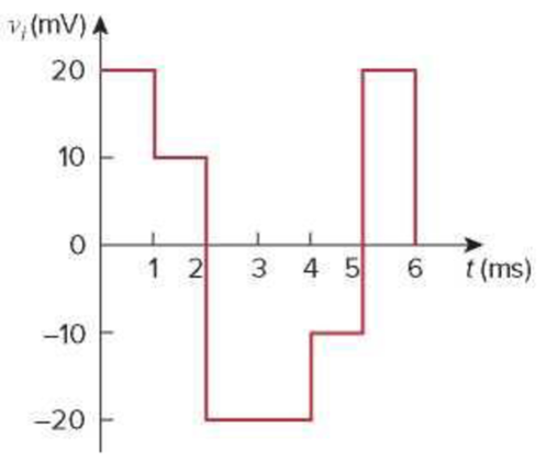
Figure 6.88
For Prob. 6.69.
Sketch the output voltage waveform of an op-amp integrator.
Explanation of Solution
Given data:
The value of the resistor
The value of the capacitor
Refer to Figure 6.88 in the textbook.
Formula used:
Write the expression to calculate the output voltage of an op-amp integrator.
Here,
Calculation:
Substitute
The given input voltage waveform is redrawn as Figure 1.
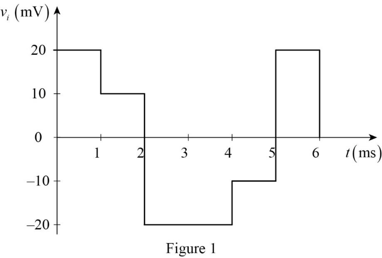
Refer to Figure 1, the input voltage
Case (i): For
Substitute
Simplify the equation to find
Substitute
Case (ii): For
Equation (2) can be rewritten as following equation to find the output voltage for
Substitute
Simplify the equation to find
Substitute
Case (iii): For
Equation (2) can be rewritten as following equation to find the output voltage for
Substitute
Simplify the equation to find
Substitute
Case (iv): For
Equation (2) can be rewritten as following equation to find the output voltage for
Substitute
Simplify the equation to find
Substitute
Case (v): For
Equation (2) can be rewritten as following equation to find the output voltage for
Substitute
Simplify the equation to find
Substitute
Therefore, the output voltage function for Figure 1 is expressed as,
The output voltage waveform is drawn as Figure 2.
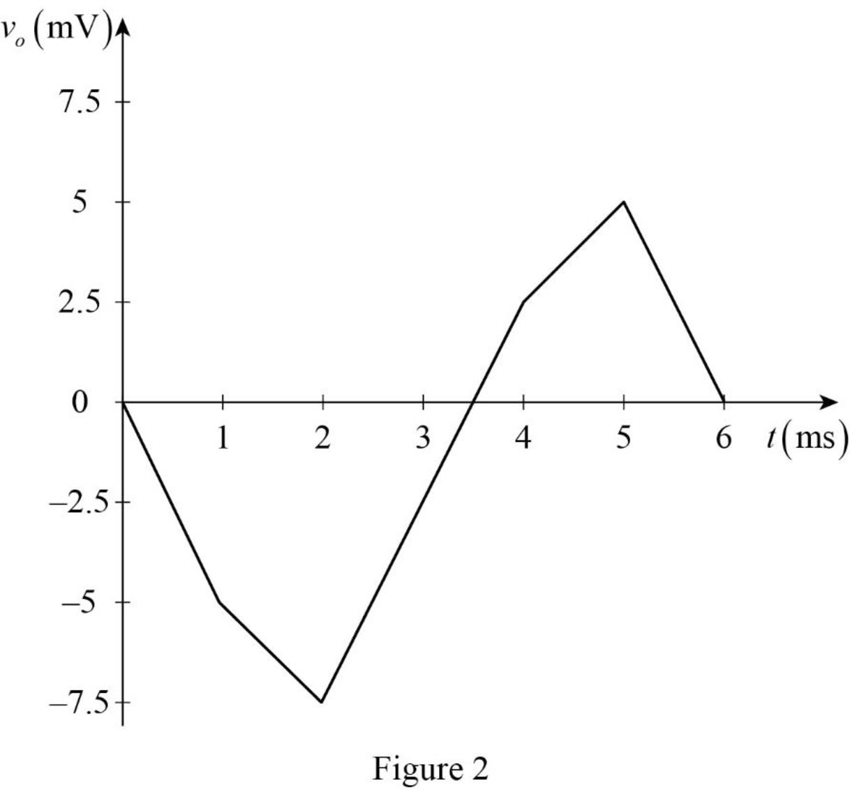
Conclusion:
Thus, the output voltage waveform of an op-amp integrator is sketched.
Want to see more full solutions like this?
Chapter 6 Solutions
EBK FUNDAMENTALS OF ELECTRIC CIRCUITS


- What are the four conditions that must be met before a generator is connected to a 3 phase system?arrow_forwardPlease solve this question step by step and handwritten and do not use chat gpt or ai tools thank you very much!arrow_forwardPlease solve question c and d step by step and handwritten and do not use chat gpt or ai tools thank you very much!arrow_forward
- Please solve questions d,e,f step by step and handwritten and do not use chat gpt or ai tools thank you very much!arrow_forwardPlease solve this question step by step and handwritten and do not use chat gpt or ai tools thank you very much!arrow_forwardPlease solve question c,d,e step by step and handwritten and do not use chat gpt or ai tools thank you very much!arrow_forward
- Q1: Design a logic circuit for the finite-state machine described by the assigned table in Fig. 1: Using D flip-flops. a. b. Using T flip-flops. Present Next State Output State x=0 x=0 YE Y₁Y Y₁Y Z 00 00 01 0 0 от 00 0 0 10 00 10 11 00 10 0arrow_forwardFind Va and Vb using mesh analysisarrow_forwardFind Va and Vb using Mesh analysisarrow_forward
- Find Va and Vb using nodal analysisarrow_forward2. Using the approximate method, hand sketch the Bode plot for the following transfer functions. a) H(s) = 10 b) H(s) (s+1) c) H(s): = 1 = +1 100 1000 (s+1) 10(s+1) d) H(s) = (s+100) (180+1)arrow_forwardQ4: Write VHDL code to implement the finite-state machine described by the state Diagram in Fig. 1. Fig. 1arrow_forward
 Introductory Circuit Analysis (13th Edition)Electrical EngineeringISBN:9780133923605Author:Robert L. BoylestadPublisher:PEARSON
 Delmar's Standard Textbook Of ElectricityElectrical EngineeringISBN:9781337900348Author:Stephen L. HermanPublisher:Cengage Learning
 Programmable Logic ControllersElectrical EngineeringISBN:9780073373843Author:Frank D. PetruzellaPublisher:McGraw-Hill Education
 Fundamentals of Electric CircuitsElectrical EngineeringISBN:9780078028229Author:Charles K Alexander, Matthew SadikuPublisher:McGraw-Hill Education
 Electric Circuits. (11th Edition)Electrical EngineeringISBN:9780134746968Author:James W. Nilsson, Susan RiedelPublisher:PEARSON
 Engineering ElectromagneticsElectrical EngineeringISBN:9780078028151Author:Hayt, William H. (william Hart), Jr, BUCK, John A.Publisher:Mcgraw-hill Education,