
Concept explainers
Videos
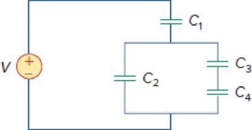
Using Fig. 6.57, design a problem that will help other students better understand how capacitors work together when connected in series and in parallel.
Figure 6.57
Design a problem to make better understand how capacitors work together when connected in series and in parallel using Figure 6.57.
Explanation of Solution
Problem design:
For the circuit in Figure 6.57, determine the voltage across each capacitor and the energy stored in each capacitor.
Formula used:
Write the expression to calculate the energy stored in the capacitor.
Here,
Calculation:
Refer to Figure 6.57 in the textbook. The Figure 6.57 is redrawn as Figure 1 by assuming the voltage and capacitor values.
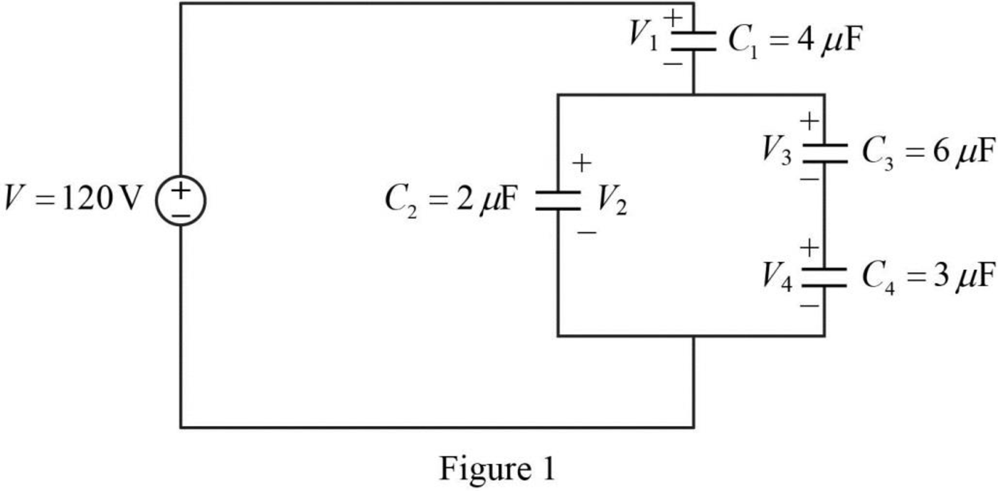
Refer to Figure 1, the capacitors
Write the expression to calculate the equivalent capacitance 1 for the series connected capacitors
Here,
Substitute
The reduced circuit of the Figure 1 is drawn as Figure 2.
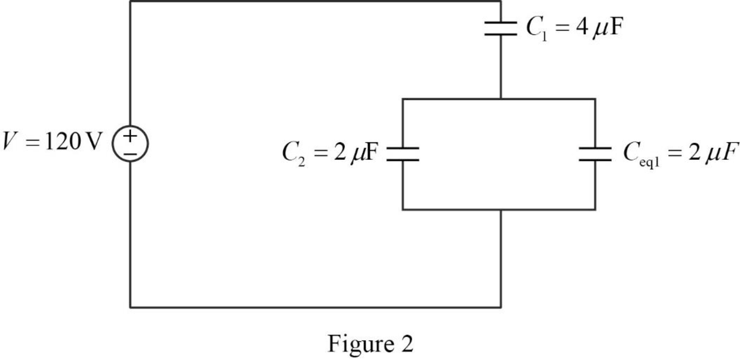
Refer to Figure 2, the capacitors
Write the expression to calculate the equivalent capacitance 2 for the parallel connected capacitors
Here,
Substitute
The reduced circuit of the Figure 2 is drawn as Figure 3.
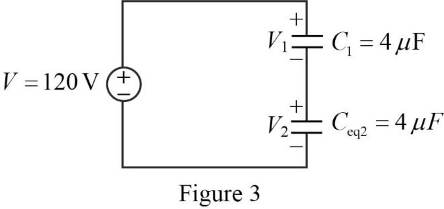
Write the expression to calculate the total applied voltage.
Here,
From the Figure 3, it is clear that the voltage across the capacitors with same capacitance value is equal. Therefore,
Substitute
Simplify the above equation to find
Therefore, from equation (5),
Write the expression to calculate the charge across the capacitor 1.
Here,
Substitute
Write the expression to calculate the charge across the capacitor 2.
Substitute
Refer to Figure 2, the capacitors
The combination of the series connected capacitors
Write the expression to calculate the voltage across the capacitor 3.
Substitute
Write the expression to calculate the voltage across the capacitor 4.
Substitute
Re-write the equation (1) to calculate the energy stored in capacitor
Substitute
Re-write the equation (1) to calculate the energy stored in capacitor
Substitute
Re-write the equation (1) to calculate the energy stored in capacitor
Substitute
Re-write the equation (1) to calculate the energy stored in capacitor
Substitute
Therefore, the value of the voltage across the capacitor 1
Conclusion:
Thus, the problem to make better understand how capacitors work together when connected in series and in parallel using Figure 6.57 is designed.
Want to see more full solutions like this?
Chapter 6 Solutions
EBK FUNDAMENTALS OF ELECTRIC CIRCUITS


- please solve manually. I need the drawing and the values too. Thank you!arrow_forwardTwo alternators, Y-connected 6.6 kV supply a load of 3000 kW at 0.8 p.f lagging. The synchronous mpedance of first alternator is (0.5+j10) Q/ph and second alternator is (0.4+j12) /ph. First alternator delivers 150 amp at 0.875 lag p.f. The two alterators are shared load equally. Determine the current, p.f., induced e.m.f, load angel, and maximum developed power of each alternator?arrow_forwardA domestic load of 2300 kW at 0.88 p.f lagging and a motors load of 3400 kW at 0.85 p.f lagging are supplied by two alternators operating in parallel. If one alternator is delivering a load of 3300 kW at 0.9 p.f lagging, what will be the output power and p.f of the other alternator?arrow_forward
- Determine the value of Rr that necessary for the circuit in Fig.(2) to operate as an oscillator and then determine the frequency of oscillation. 0.001 F 0.001 F 0.001 F R₁ • 10 ΚΩ R₁ 10 k R • 10 ΚΩarrow_forward(a) For the circuit shown in Figure Q3(a) (RFC and Cc are forbias) (i) (ii) Draw the AC small signal equivalent circuit of the oscillator. From this equivalent circuit derive an equation for fo and the gain condition for the oscillations to start. VDD www RG eee RFC H Cc 北 5 C₁ L 000 C₂ Voarrow_forwardPlease solve this question step by step handwritten solution and do not use chat gpt or any ai toolsfor part ii) you may need to use nodal analysisarrow_forward
- 12.1. Find the steady-state response vo (t) for the network. 00000- 1Ω ww 12 cos(t) V + www 202 1 H 202 1 F + 1Ω νο -arrow_forwardA Three-phase, 12 pole, Y-connected alternator has 108 slots and 14 conductors per slot. The windings are (5/6 th) pitched. The flux per pole is 57 mWb distributed sinusoidally over the pole. If the machine runs at 500 r.p.m., determine the following: (a) The frequency of the generated e.m.f., (b) The distribution factor, (c) The pitch factor, and (d) The phase and line values of the generated e.m.f.?arrow_forwardTwo 3-ph, 6.6 kV, Y-connected, alternators supply a load of 3000 kW at 0.8 p.f. lagging. The synchronou impedance per phase of machine A is (0.5+110) and that of machine B is (0.4 +J12) . The excitation of machine A adjusted so that it delivers 150 A. The load is shared equally between the machines. Determine the armature curre p.f., induced e.m.f., and load angle of each machine?arrow_forward
- Name the circuit below? The output voltage is initially zero and the pulse width is 200 μs. Find the Vout and draw the output waveform? +2.5 V V 247 -2.5 V C 0.01 F Ri W 10 ΚΩarrow_forwardPlease work outarrow_forwardFind Vfinal when Vs up and Vs V. Which LED will light in each case? Red or Green? Justify your answers. Fill the table below. Vs 8 ΚΩ Vos Χρι + 3 ΚΩ www 6 ΚΩ ww 4 ΚΩ Yo www Vo Vec-12 V Nol V final Vm w 3 ΚΩ 5 V 38 ΚΩ R= 1 kQ V -12 V Red LED Green LED Vs Vo Vfinal Which LED is ON? Varrow_forward
 Delmar's Standard Textbook Of ElectricityElectrical EngineeringISBN:9781337900348Author:Stephen L. HermanPublisher:Cengage Learning