
Concept explainers
Videos
The inductors in Fig. 6.87 are initially charged and are connected to the black box at t = 0. If i1(0) = 4 A, i2(0) = −2 A, and v(t) = 50e−200t mV, t ≥ 0, find:
- (a) the energy initially stored in each inductor,
- (b) the total energy delivered to the black box from t = 0 to t = ∞,
- (c) i1(t) and i2(t), t ≥ 0,
- (d) i(t), t ≥ 0.
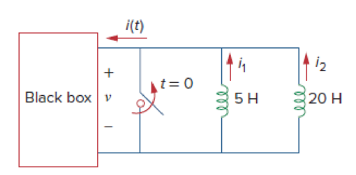
Figure 6.87
For Prob. 6.65.
(a)
Calculate the initial energy stored in each inductor for the given initial conditions.
Answer to Problem 65P
The energy stored initially in each inductor
Explanation of Solution
Given data:
The Black box connects across the initially charged inductors at
The initial current of inductor
The initial current of inductor
The voltage across the inductors and black box is same. That is,
Formula used:
Write the formula to find the energy stored in an inductor.
Calculation:
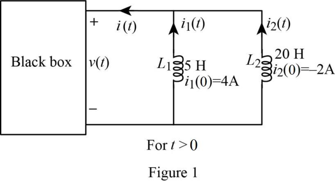
Re-draw the given figure as shown in Figure 1.
Using the formula in equation (1), the energy stored initially in inductor
Substitute
Using the formula in equation (1), the energy stored initially in inductor
Substitute
Conclusion:
Thus, the energy stored initially in each inductor
(b)
Calculate the total energy delivered to the black box by the inductors for
Answer to Problem 65P
The total energy delivered to the black box by the inductors is
Explanation of Solution
Given data:
Refer to Part (a).
Formula used:
Write the formula to find the total energy delivered to the black box by the inductors from
Here,
Calculation:
The total energy delivered to the black box in period of
Substitute
Conclusion:
Thus, the total energy delivered to the black box by the inductors is
(c)
Calculate the currents in each inductor for the period of
Answer to Problem 65P
The currents
Explanation of Solution
Given data:
Refer to Part (a).
Formula used:
Write the formula to find the current through an inductor.
Here,
Calculation:
Using the formula in equation (3), the current through an inductor
Since the black box and both inductors are in parallel,
Substitute
In the Figure 1, currents
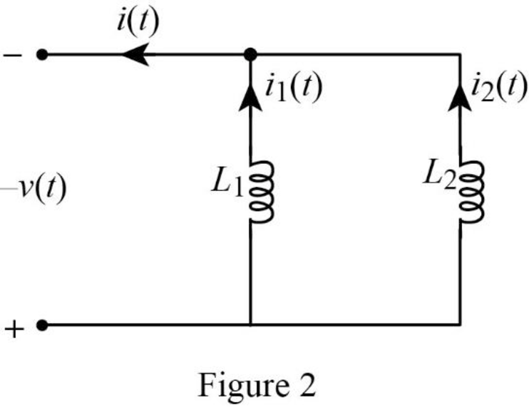
From Figure 2, the current
Substitute
Reduce the equation as follows.
Using the formula in equation (3), the current
Substitute
Consider reversing polarities for voltage
Substitute
Reduce the equation as follows.
Conclusion:
Thus, the currents
(d)
Find the current
Answer to Problem 65P
The current
Explanation of Solution
Given data:
Refer to part (a).
Formula used:
Write the formula for the current
Here,
Calculation:
Refer to part (c), the currents
Substitute
Conclusion:
Thus, the current
Want to see more full solutions like this?
Chapter 6 Solutions
EBK FUNDAMENTALS OF ELECTRIC CIRCUITS


- Circuits help please solve and explain. Question in images providedarrow_forward+ V 6.2 A 1.2 A S R 4 Ω Find the source voltage Vs 0.8 Aarrow_forwardDetermine i(t) for t≥ 0 given that the circuit below had been in steady state for a long time prior to t = 0. Also, I₁ = 1 5 A, R₁ =22, R2 =10 Q2, R3 = 32, R4 =7 2, and L=0.15 H. Also fill the table. m L ww R2 t = 0 R₁ 29 R3 R4 Time 0 iL(t) 0 8arrow_forward
- Find the Thévenin equivalent circuit for the portions of the networks in Figure external to the elements between points a and b. a R₁ 2002 I = 0.1 A 0° Xc : 32 Ω R2 = 6802 20 Ω фъarrow_forwardFind the Norton equivalent circuit for the network external to the elements between a and b for the networks in Figure. E1 = 120 V Z 0° R ww 10 Ω Xc XL · 000 802 802 ① I = 0.5 AZ 60° ZL barrow_forwardUsing superposition, determine the current through inductance XL for each network in Figure I = 0.3 A 60° XL 000 802 XC 502 Ω E 10 V0° =arrow_forward
- Find the Thévenin equivalent circuit for the portions of the networks in Figure external to the elements between points a and b. E = 20 VZ0° + R ww 2 ΚΩ Хо XL 000 6ΚΩ 3 ΚΩ b RLarrow_forwardWhat percentage of the full-load current of a thermally protected continuous-duty motor of more than one Hp can the trip current be, if the full-load current is 15 amperes? Ο 122 Ο 140 156 O 170arrow_forwardQ3arrow_forward
 Introductory Circuit Analysis (13th Edition)Electrical EngineeringISBN:9780133923605Author:Robert L. BoylestadPublisher:PEARSON
 Delmar's Standard Textbook Of ElectricityElectrical EngineeringISBN:9781337900348Author:Stephen L. HermanPublisher:Cengage Learning
 Programmable Logic ControllersElectrical EngineeringISBN:9780073373843Author:Frank D. PetruzellaPublisher:McGraw-Hill Education
 Fundamentals of Electric CircuitsElectrical EngineeringISBN:9780078028229Author:Charles K Alexander, Matthew SadikuPublisher:McGraw-Hill Education
 Electric Circuits. (11th Edition)Electrical EngineeringISBN:9780134746968Author:James W. Nilsson, Susan RiedelPublisher:PEARSON
 Engineering ElectromagneticsElectrical EngineeringISBN:9780078028151Author:Hayt, William H. (william Hart), Jr, BUCK, John A.Publisher:Mcgraw-hill Education,