
CONTROL SYSTEMS ENGINEERING - WILEYPLUS
7th Edition
ISBN: 9781119143277
Author: NISE
Publisher: WILEY
expand_more
expand_more
format_list_bulleted
Concept explainers
Videos
Textbook Question
Chapter 6, Problem 69P
Hybrid vehicle. Figure P6.l8 shows the HEV system presented in Chapter 5, where parameter values have
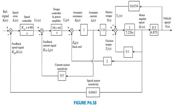
been substituted. It is assumed here that the speed controller has a proportional gain, Kp, to be adjusted. Use the Routh-Hurwitz stability method to find the range of positive Kp, for which the system is closed-loop stable (Graebe, I995).
Expert Solution & Answer
Want to see the full answer?
Check out a sample textbook solution
Students have asked these similar questions
Compute the mass fraction of eutectoid cementite
in an iron-carbon alloy that contains 1.00 wt% C.
Compute the mass fraction of eutectoid cementite
in an iron-carbon alloy that contains 1.00 wt% C.
!
Required information
Mechanical engineering, don't use
chatgpt.
Thanks
A 60-kip-in. torque T is applied to each of the cylinders shown.
NOTE: This is a multi-part question. Once an answer is submitted, you will be unable to return to this part.
3 in.
4 in.
(a)
(b)
Determine the inner diameter of the 4-in. diameter hollow cylinder shown, for which the maximum stress is the same as in part a.
The inner diameter is
in.
Chapter 6 Solutions
CONTROL SYSTEMS ENGINEERING - WILEYPLUS
Ch. 6 - Prob. 1RQCh. 6 - Prob. 2RQCh. 6 - What would happen to a physical system chat...Ch. 6 - Why are marginally stable systems considered...Ch. 6 - Prob. 5RQCh. 6 - Prob. 6RQCh. 6 - Prob. 7RQCh. 6 - Prob. 8RQCh. 6 - Prob. 9RQCh. 6 - Why do we sometimes multiply a row of a Routh...
Ch. 6 - Prob. 11RQCh. 6 - Prob. 12RQCh. 6 - 13. Does the presence of an entire row of zeros...Ch. 6 - Prob. 14RQCh. 6 - Prob. 15RQCh. 6 - Prob. 16RQCh. 6 - Tell how many roots of the following polynomial...Ch. 6 - Tell how many roots of the following polynomial...Ch. 6 - Using the Routh table, tell how many poles of the...Ch. 6 - Prob. 4PCh. 6 - Determine how many closed-loop poles lie in the...Ch. 6 - Determine how many closed-loop poles lie in the...Ch. 6 - MATLAB ML 7. Use MATLAB to find the pole location...Ch. 6 - Symbolic Math SM 8. Use MATLAB and the Symbolic...Ch. 6 - Determine whether the unity feedback system of...Ch. 6 - Use MATLAB to find the pole locations for the...Ch. 6 - Consider the unity feedback system of Figure P6.3...Ch. 6 - In the system of Figure P6.3, let Gs=Ks+1ss2s+3...Ch. 6 - Given the unity feedback system of Figure P6.3...Ch. 6 - Using the Routh-Hurwitz criterion and the unity...Ch. 6 - Given the unity feedback system of Figure P6.3...Ch. 6 - Repeat Problem 15 using MATLAB.Ch. 6 - Prob. 17PCh. 6 - For the system of Figure P6.4, tell how many...Ch. 6 - Using the Routh-Hurwitz criterion, tell how many...Ch. 6 - Determine if the unity feedback system of Figure...Ch. 6 - For the unity feedback system of Figure P6.3 with...Ch. 6 - In the system of Figure P6.3, let Gs=Ksassb Find...Ch. 6 - For the unity feedback system of Figure P63 with...Ch. 6 - Find the range of K for stability for the unity...Ch. 6 - For the unity feedback system of Figure P6.3 with...Ch. 6 - find the range of K for stability. [Section: 6.41]...Ch. 6 - Find the range of gain, K, to ensure stability in...Ch. 6 - Using the Routh-Hurwitz criterion, find the value...Ch. 6 - Use the Routh-Hurwitz criterion to find the range...Ch. 6 - Prob. 32PCh. 6 - Given the unity feedback system of Figure P63 with...Ch. 6 - Repeat Problem 33 for [Section: 6.4]...Ch. 6 - For the system shown in Figure P6.8, find the...Ch. 6 - Given the unity feedback system of Figure P6.3...Ch. 6 - For the unity feedback system of Figure P6.3 with...Ch. 6 - For the unity feedback system of Figure P6.3 with...Ch. 6 - Given the unity feedback system of Figure P6.3...Ch. 6 - Using the Routh-Hurwitz criterion and the unity...Ch. 6 - Find the range of K to keep the system shown in...Ch. 6 - Prob. 43PCh. 6 - The closed-loop transfer function of a system is...Ch. 6 - Prob. 45PCh. 6 - Prob. 46PCh. 6 - An interval polynomial is of the form...Ch. 6 - A linearized model of a torque-controlled crane...Ch. 6 - The read/write head assembly arm of a computer...Ch. 6 - A system is represented in state space as...Ch. 6 - State Space SS 52. The following system in state...Ch. 6 - Prob. 54PCh. 6 - A model for an airplane’s pitch loop is shown in...Ch. 6 - Prob. 57PCh. 6 - Prob. 58PCh. 6 - Prob. 59PCh. 6 - Prob. 60PCh. 6 - Prob. 61PCh. 6 - Look-ahead information can be used to...Ch. 6 - Prob. 63PCh. 6 - It has been shown (Pounds, 2011) that an unloaded...Ch. 6 - Prob. 65PCh. 6 - The system shown in Figure P6.16 has G1s=1/ss+2s+4...Ch. 6 - Prob. 67PCh. 6 - Prob. 68PCh. 6 - Hybrid vehicle. Figure P6.l8 shows the HEV system...Ch. 6 - Prob. 70P
Knowledge Booster


Learn more about
Need a deep-dive on the concept behind this application? Look no further. Learn more about this topic, mechanical-engineering and related others by exploring similar questions and additional content below.Similar questions
- Mechanical engineering, Don't use chatgpt. Strict warning.arrow_forward10:38 PM P 4136 54 A man Homework was due west for and 4km. He then changes directies walks on a bearing south-wes IS How far Point? of 1970 until he of his Starting Port Is he then from his stating What do you think about ... ||| Մ כarrow_forwardA simply supported T-shaped beam of 6m in length has to be designed to carry an inclined central point load W. Find the max- imum value of this load such that the maximum tensile and com- pression stresses on the beam do not exceed 30 and 60 respectively. N mm² N mm², 90 mm 80 mm Y W 60 mm 30° 10 mm 10 mm Xarrow_forward
- Problem 9.5 9.5 A 1080-kg car is parked on a sloped street. The figure shows its wheels and the position of its center of mass. The street is icy, and as a result the coefficient of static friction between the car's tires and the street surface is μs = 0.2. Determine the steepest slope (in degrees relative to the horizontal) at which the car could remain in equilibrium if a. the brakes are applied to both its front and rear wheels; b. the brakes are applied to the front (lower) wheels only. Problem 9.5 1380 mm 532 mm 2370 mmarrow_forwardCan someone explain please with conversionsarrow_forwardCorrect Answer is written below. Detailed and complete fbd only please. I will upvote, thank you. 1: The assembly shown is composed of a rigid plank ABC, supported by hinge at A, spring at B and cable at C.The cable is attached to a frictionless pulley at D and rigidly supported at E. The cable is made of steel with E = 200,000MPa and cross-sectional area of 500 mm2. The details of pulley at D is shown. The pulley is supported by a pin, passingthough the pulley and attached to both cheeks. Note that E is directly above B.Given: H = 3 m; L1 = 2 m; L2 = 4 m; w = 12 kN/m; x:y = 3:4Spring Parameters:Wire diameter = 30 mmMean Radius = 90 mmNumber of turns = 12Modulus of Rigidity = 80 GPaAllowable stresses:Allowable shear stress of Pin at D = 85 MPaAllowable normal stress of cheek at D = 90MPaAllowable bearing stress of cheek at D = 110MPa1. Calculate the reaction of spring Band tension in cable at C.2. Calculate the vertical displacementat C and the required diameter ofpin at D.3.…arrow_forward
- Correct answer and complete fbd only. I will upvote. The compound shaft, composed of steel,aluminum, and bronze segments, carries the two torquesshown in the figure. If TC = 250 lb-ft, determine the maximumshear stress developed in each material (in ksi). The moduliof rigidity for steel, aluminum, and bronze are 12 x 106 psi, 4x 10⁶ psi, and 6 x 10⁶ psi, respectivelyarrow_forwardCan you explain the algebra steps that aren't shown but stated to be there, on how to get this equationarrow_forwardCorrect answer and complete fbd only. I will upvote. A flanged bolt coupling consists of two concentric rows of bolts. The inner row has 6 nos. of 16mm diameterbolts spaced evenly in a circle of 250mm in diameter. The outer row of has 10 nos. of 25 mm diameter bolts spaced evenly in a circle of 500mm in diameter. If the allowable shear stress on one bolt is 60 MPa, determine the torque capacity of the coupling. The Poisson’s ratio of the inner row of bolts is 0.2 while that of the outer row is 0.25 and the bolts are steel, E =200 GPa.arrow_forward
- Correct answer and complete fbd only. I will upvote. 10: The constant wall thickness of a steel tube with the cross sectionshown is 2 mm. If a 600-N-m torque is applied to the tube. Use G = 80 GPa forsteel.1. Find the shear stress (MPa) in the wall of the tube.2. Find the angle of twist, in degrees per meter of length.arrow_forwardCORRECT ANSWER WITH COMPLETE FBD ONLY. I WILL UPVOTE. A torque wrench is used to tighten the pipe shown.Dimensions: S1 = 400 mm; S2 = 250 mm; S3 = 100 mmModulus of Rigidity G = 78 GPa1. The diameter of the solid pipe is 20 mm. How much is themaximum force P (N) that can be applied based on theallowable shear stress of 60 MPa?2. For a hollow pipe with 50 mm outside diameter and is 6 mmthick, compute for the maximum force P (kN) that can beapplied such that the angle of twist at A does not exceed 5degrees.3. The torque applied to tighten the hollow pipe is 200 N-m.Given: Pipe outside diameter = 50 mm Pipe thickness = 6 mmSolve for the resulting maximum shear stress (MPa) in the pipe.arrow_forwardCorrect answer and complete fbd only. I will upvote. 6: The shaft carries a total torque T0 that is uniformly distributedover its length L. Determine the angle of twist (degrees) of the shaft in termsif T0 = 1.2 kN-m, L = 2 m, G = 80 GPa, and diameter = 120 mm.arrow_forward
arrow_back_ios
SEE MORE QUESTIONS
arrow_forward_ios
Recommended textbooks for you
 Principles of Heat Transfer (Activate Learning wi...Mechanical EngineeringISBN:9781305387102Author:Kreith, Frank; Manglik, Raj M.Publisher:Cengage Learning
Principles of Heat Transfer (Activate Learning wi...
Mechanical Engineering
ISBN:9781305387102
Author:Kreith, Frank; Manglik, Raj M.
Publisher:Cengage Learning
Introduction to Undamped Free Vibration of SDOF (1/2) - Structural Dynamics; Author: structurefree;https://www.youtube.com/watch?v=BkgzEdDlU78;License: Standard Youtube License