Concept explainers
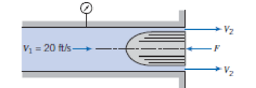
Water flows at low speed through a circular tube with inside diameter of 2 in. A smoothly contoured body of 1.5 in. diameter is held in the end of the tube where the water discharges to atmosphere. Neglect frictional effects and assume uniform velocity profiles at each section. Determine the pressure measured by the gauge and the force required to hold the body.

P6.62
Trending nowThis is a popular solution!

Chapter 6 Solutions
Fox And Mcdonald's Introduction To Fluid Mechanics
Additional Engineering Textbook Solutions
Introduction To Programming Using Visual Basic (11th Edition)
Problem Solving with C++ (10th Edition)
Vector Mechanics for Engineers: Statics and Dynamics
Java How to Program, Early Objects (11th Edition) (Deitel: How to Program)
Starting Out with Java: From Control Structures through Data Structures (4th Edition) (What's New in Computer Science)
Electric Circuits. (11th Edition)
- solve belowarrow_forward4. The system in Fig. consists of 1200 m (length) of 0.05 m (diameter) cast iron pipe, two 45° long-radius elbows, four 90° flanged long-radius elbows, and a fully open globe valve. If the elevation at point 1 is 400 m, what gage pressure is required at point 1 to deliver 0.005 m³/s of water at 20°C into the reservoir? Average surface roughness of cast iron is ε = 0.26 mm. For water at 20°C, take density, p = 998 kg/m³; dynamic viscosity, μ = 0.001 Pa-s; and acceleration due to gravity, g = 9.81 m/s². 90° elbow: KL90, elbow K₁ = 0.5 ent Elevation (1 400 m = 0.3 45° elbow: KL45,elbow=0.2 Elevation 500 m ! Sharp exit Open KL = 10 globe valve Klexit = 1arrow_forwardWater in a vertical (i.e., gravitational force of the fluid in the nozzle plays a role, and the elevation change in the Bernoulli's Equation, if needed, should be considered) pipe is charging from an attached bend nozzle into the atmosphere as shown in Fig. 5. The nozzle's weight is 20 kg. The pipe and the nozzle are connected by a flange. The gage pressure of the flow at the flange is 35 kPa when the discharge rate is 0.1 m³/s. The volume of the bending nozzle is 0.012 m³. Calculate the vertical component of the anchoring forcing required to hold the nozzle in place and determine its direction. G= 9.81 m/s². The density of water is 1000 kg/m³. ChatGPT solution: Nozzle 1 Area -0.01 m² P-35 kPa Area -0.025 m² 0.10 ms Figure 5: Q5 35 degreearrow_forward
- CalculatorWater flows through a horizontal duct of diameter 0.5 m with a velocity of 0.4 m/s. If the friction factor is 0.002 calculate the pressure difference between two points 24.8 m apart. Assume the density of water is 1000 kg/m3 Your answer should be in Pascalsarrow_forwardSubject :Fluid mechanics Give me right solution. Help me urgentarrow_forwardRead carefully and solve this problem correctly ?arrow_forward
- 1. A pipe 100 mm bore diameter carries oil of density 900 kg/m3 at a rate of 4 kg/s. The pipe reduces to 60 mm bore diameter and rises 120 m in altitude. The pressure at this point is atmospheric (zero gauge). Assuming no frictional losses, determine: i. The volume/s (4.44 dm³/s) ii. The velocity at each section (0.566 m/s and 1.57 m/s) iii. The pressure at the lower end. (1.06 MPa)arrow_forwardA 0.4 m-diameter pipe bend shown in the diagram is carrying crude oil (S = 0.65) with a steady flow with velocity of 3 m/s. The bend has an angle of 30° and lies in a vertical plane. The volume of oil in the bend is 1.2 m3, and the empty weight of the bend is 4 kN. Assume the pressure along the centerline of the bend is constant with a value of 85 kPa gage. Water density = 1000 kg/m3, g= 9.81 m/s?, Patm = 100 kPa, frictionless flow. Answer the following: Bolted flange Flow 30 The net pressure force along the horizontal direction (N). Net out flow rate of momentum through the control surface (N) in the horizontal direction. Absolute value.arrow_forwardDon't give handwritten solution.arrow_forward
- i need the answer quicklyarrow_forwardWater is transported in a pipe, at an average flow rate of Q = 50 L/s. Calculate the pressure difference p between the 2 manometers. We can assume that the energy losses by friction are negligible, and that there are only singular energy losses (be careful to identify ALL the singularities). The pump adds an energy of HP = 10 m to the system. "GATE VALVE" P2 OUVERTURE COMPLÈTE do = 150 mm Q = 50 L/s • 2) 2 m Q = 50 L/s COUDES À POMPE RAYONS COURTS do = 150 mm (Hp = 10 m)arrow_forwardA1,A2arrow_forward
 Elements Of ElectromagneticsMechanical EngineeringISBN:9780190698614Author:Sadiku, Matthew N. O.Publisher:Oxford University Press
 Mechanics of Materials (10th Edition)Mechanical EngineeringISBN:9780134319650Author:Russell C. HibbelerPublisher:PEARSON
 Thermodynamics: An Engineering ApproachMechanical EngineeringISBN:9781259822674Author:Yunus A. Cengel Dr., Michael A. BolesPublisher:McGraw-Hill Education
 Control Systems EngineeringMechanical EngineeringISBN:9781118170519Author:Norman S. NisePublisher:WILEY
 Mechanics of Materials (MindTap Course List)Mechanical EngineeringISBN:9781337093347Author:Barry J. Goodno, James M. GerePublisher:Cengage Learning
 Engineering Mechanics: StaticsMechanical EngineeringISBN:9781118807330Author:James L. Meriam, L. G. Kraige, J. N. BoltonPublisher:WILEY


