
VECTOR MECHANICS FOR ENGINEERS: STATICS
12th Edition
ISBN: 9781259977121
Author: BEER
Publisher: MCG
expand_more
expand_more
format_list_bulleted
Concept explainers
Videos
Textbook Question
Chapter 6, Problem 6.174RP
A couple M with a magnitude of 1.5 kN·m is applied to the crank of the engine system shown. For each of the two positions shown, determine the force P required to hold the system in equilibrium.
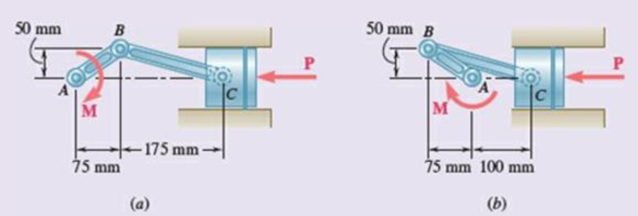
Fig. P6.174
Expert Solution & Answer
Want to see the full answer?
Check out a sample textbook solution
Students have asked these similar questions
8. All of the members in the Warren truss of Figure 8 are of length 10 ft. Use the method of
sections to determine the forces in the members BD,CD,CE.
B
A
C
D
E
F
G
2000 lb
3000 lb
5000 lb
Figure 8
H
An acrobat is walking on a tightrope of length L
=20.1 m attached to supports A and B at a
distance of 20.0 m apart. The combined weight
of the acrobat and his balancing pole is 900 N,
and the friction between his shoes and the rope
is large enough to prevent him from slipping.
Neglecting the weight of the rope and any
elastic deformation, determine the deflection (y)
and the tension in portion AC and BC of the
rope for values of x from 0.5 m to 10 m using
0.5 m increments.
1. Determine the maximum deflection (y) in
the rope.
2. Plot tension of AC and BC vs. x (on the
same plot with x on the x-axis). Turn in the
plot and the table of x, TAC, and TBC (clearly
label each).
A
C
20.0 m
B
5. A 4000 lb block of concrete is attached by light inextensible cables to the truss in Figure 5.
Determine the force in each member. State whether each member is in tension or compression.
3
ΘΑ
D
E
cables
all dimensions in feet.
Chapter 6 Solutions
VECTOR MECHANICS FOR ENGINEERS: STATICS
Ch. 6.1 - Using the method of joints, determine the force in...Ch. 6.1 - Using the method of joints, determine the force in...Ch. 6.1 - Using the method of joints, determine the force in...Ch. 6.1 - Using the method of joints, determine the force in...Ch. 6.1 - Using the method of joints, determine the force in...Ch. 6.1 - Using the method of joints, determine the force in...Ch. 6.1 - Using the method of joints, determine the force in...Ch. 6.1 - Using the method of joints, determine the force in...Ch. 6.1 - Using the method of joints, determine the force in...Ch. 6.1 - Determine the force in each member of the truss...
Ch. 6.1 - Determine the force in each member of the Gambrel...Ch. 6.1 - Determine the force in each member of the Howe...Ch. 6.1 - Using the method of joints, determine the force in...Ch. 6.1 - Prob. 6.14PCh. 6.1 - Determine the force in each member of the Warren...Ch. 6.1 - Solve Problem 6.15 assuming that the load applied...Ch. 6.1 - Determine the force in each member of the Pratt...Ch. 6.1 - The truss shown is one of several supporting an...Ch. 6.1 - Determine the force in each member of the Pratt...Ch. 6.1 - Solve Problem 6.19 assuming that the load applied...Ch. 6.1 - Determine the force in each of the members located...Ch. 6.1 - Determine the force in member DE and in each of...Ch. 6.1 - Determine the force in each of the members located...Ch. 6.1 - The portion of truss shown represents the upper...Ch. 6.1 - For the tower and loading of Prob. 6.24 and...Ch. 6.1 - Solve Problem 6.24 assuming that the cables...Ch. 6.1 - Determine the force in each member of the truss...Ch. 6.1 - Determine the force in each member of the truss...Ch. 6.1 - Determine whether the trusses of Problems 6.31a,...Ch. 6.1 - Determine whether the trusses of Problems 6.31b,...Ch. 6.1 - For the given loading, determine the zero-force...Ch. 6.1 - For the given loading, determine the zero-force...Ch. 6.1 - For the given loading, determine the zero-force...Ch. 6.1 - Determine the zero-force members in the truss of...Ch. 6.1 - The truss shown consists of six members and is...Ch. 6.1 - The truss shown consists of six members and is...Ch. 6.1 - The truss shown consists of six members and is...Ch. 6.1 - Prob. 6.38PCh. 6.1 - The truss shown consists of nine members and is...Ch. 6.1 - Solve Prob. 6.39 for P = 0 and Q = (900 N)k. 6.39...Ch. 6.1 - The truss shown consists of 18 members and is...Ch. 6.1 - The truss shown consists of 18 members and is...Ch. 6.2 - Determine the force in members BD and DE of the...Ch. 6.2 - Determine the force in members DG and EG of the...Ch. 6.2 - Determine the force in members BD and CD of the...Ch. 6.2 - Determine the force in members DF and DG of the...Ch. 6.2 - A floor truss is loaded as shown. Determine the...Ch. 6.2 - A floor truss is loaded as shown. Determine the...Ch. 6.2 - Determine the force in members CD and DF of the...Ch. 6.2 - Determine the force in members CE and EF of the...Ch. 6.2 - Determine the force in members DE and DF of the...Ch. 6.2 - Determine the force in members EG and EF of the...Ch. 6.2 - Determine the force in members DF and DE of the...Ch. 6.2 - Determine the force in members CD and CE of the...Ch. 6.2 - A Pratt roof truss is loaded as shown. Determine...Ch. 6.2 - A Pratt roof truss is loaded as shown. Determine...Ch. 6.2 - A Howe scissors roof truss is loaded as shown....Ch. 6.2 - A Howe scissors roof truss is loaded as shown....Ch. 6.2 - Determine the force in members AD, CD, and CE of...Ch. 6.2 - Determine the force in members DG, FG, and FH of...Ch. 6.2 - Determine the force in member GJ of the truss...Ch. 6.2 - Determine the force in members DG and FH of the...Ch. 6.2 - Prob. 6.63PCh. 6.2 - Prob. 6.64PCh. 6.2 - The diagonal members in the center panels of the...Ch. 6.2 - The diagonal members in the center panels of the...Ch. 6.2 - The diagonal members in the center panels of the...Ch. 6.2 - Solve Prob. 6.67 assuming that the 9-kip load has...Ch. 6.2 - Classify each of the structures shown as...Ch. 6.2 - Classify each of the structures shown as...Ch. 6.2 - 6.70 through 6.74 classify as determinate or...Ch. 6.2 - 6.70 through 6.74 classify as determinate or...Ch. 6.2 - 6.70 through 6.74 classify as determinate or...Ch. 6.2 - 6.70 through 6.74 classify as determinate or...Ch. 6.3 - For the frame and loading shown, draw the...Ch. 6.3 - For the frame and loading shown, draw the...Ch. 6.3 - Draw the free-body diagram(s) needed to determine...Ch. 6.3 - Knowing that the pulley has a radius of 0.5 m,...Ch. 6.3 - and 6.76 Determine the force in member BD and the...Ch. 6.3 - Prob. 6.76PCh. 6.3 - For the frame and loading shown, determine the...Ch. 6.3 - Determine the components of all forces acting on...Ch. 6.3 - The hydraulic cylinder CF, which partially...Ch. 6.3 - The hydraulic cylinder CF, which partially...Ch. 6.3 - Determine the components of all forces acting on...Ch. 6.3 - Determine the components of all forces acting on...Ch. 6.3 - Determine the components of the reactions at A and...Ch. 6.3 - Determine the components of the reactions at D and...Ch. 6.3 - Determine the components of the reactions at A and...Ch. 6.3 - Determine the components of the reactions at A and...Ch. 6.3 - Determine the components of the reactions at A and...Ch. 6.3 - The 48-lb load can be moved along the line of...Ch. 6.3 - The 48-lb load is removed and a 288-lb in....Ch. 6.3 - (a) Show that, when a frame supports a pulley at...Ch. 6.3 - Knowing that each pulley has a radius of 250 mm,...Ch. 6.3 - Knowing that the pulley has a radius of 75 mm,...Ch. 6.3 - Prob. 6.93PCh. 6.3 - Prob. 6.94PCh. 6.3 - A trailer weighing 2400 lb is attached to a...Ch. 6.3 - In order to obtain a better weight distribution...Ch. 6.3 - The cab and motor units of the front-end loader...Ch. 6.3 - Solve Problem 6.97 assuming that the 75-kN load...Ch. 6.3 - Knowing that P = 90 lb and Q = 60 lb, determine...Ch. 6.3 - Knowing that P = 90 lb and Q = 60 lb, determine...Ch. 6.3 - For the frame and loading shown, determine the...Ch. 6.3 - For the frame and loading shown, determine the...Ch. 6.3 - Prob. 6.103PCh. 6.3 - Prob. 6.104PCh. 6.3 - For the frame and loading shown, determine the...Ch. 6.3 - Solve Prob. 6.105 assuming that the 6-kN load has...Ch. 6.3 - The axis of the three-hinge arch ABC is a parabola...Ch. 6.3 - The axis of the three-hinge arch ABC is a parabola...Ch. 6.3 - 6.109 and 6.110 Neglecting the effect of friction...Ch. 6.3 - and 6.110 Neglecting the effect of friction at the...Ch. 6.3 - 6.111, 6.112, and 6.113 Members ABC and CDE are...Ch. 6.3 - 6.111, 6.112, and 6.113 Members ABC and CDE are...Ch. 6.3 - 6.111, 6.112, and 6.113 Members ABC and CDE are...Ch. 6.3 - Members ABC and CDE are pin-connected at C and...Ch. 6.3 - Solve Prob. 6.112 assuming that the force P is...Ch. 6.3 - Solve Prob. 6.114 assuming that the force P is...Ch. 6.3 - Four beams, each with a length of 2a, are nailed...Ch. 6.3 - Four beams, each with a length of 3a, are held...Ch. 6.3 - 6.119 through 6.121 Each of the frames shown...Ch. 6.3 - 6.119 through 6.121 Each of the frames shown...Ch. 6.3 - 6.119 through 6.121 Each of the frames shown...Ch. 6.4 - An 84-lb force is applied to the toggle vise at C....Ch. 6.4 - For the system and loading shown, draw the...Ch. 6.4 - A small barrel weighing 60 lb is lifted by a pair...Ch. 6.4 - The position of member ABC is controlled by the...Ch. 6.4 - The shear shown is used to cut and trim...Ch. 6.4 - A 100-lb force directed vertically downward is...Ch. 6.4 - Prob. 6.124PCh. 6.4 - The control rod CE passes through a horizontal...Ch. 6.4 - Solve Prob. 6.125 when (a) = 0, (b) = 6. Fig....Ch. 6.4 - The press shown is used to emboss a small seal at...Ch. 6.4 - The press shown is used to emboss a small seal at...Ch. 6.4 - The pin at B is attached to member ABC and can...Ch. 6.4 - The pin at B is attached to member ABC and can...Ch. 6.4 - Arm ABC is connected by pins to a collar at B and...Ch. 6.4 - Arm ABC is connected by pins to a collar at B and...Ch. 6.4 - The Whitworth mechanism shown is used to produce a...Ch. 6.4 - Solve Prob. 6.133 when (a) = 60, (b) = 90. Fig....Ch. 6.4 - and 6.136 Two rods are connected by a slider block...Ch. 6.4 - and 6.136 Two rods are connected by a slider block...Ch. 6.4 - 6.137 and 6.138 Rod CD is attached to the collar D...Ch. 6.4 - 6.137 and 6.138 Rod CD is attached to the collar D...Ch. 6.4 - Two hydraulic cylinders control the position of...Ch. 6.4 - Two hydraulic cylinders control the position of...Ch. 6.4 - A steel ingot weighing 8000 lb is lifted by a pair...Ch. 6.4 - If the toggle shown is added to the tongs of Prob....Ch. 6.4 - A 9-m length of railroad rail of mass 40 kg/m is...Ch. 6.4 - The gear-pulling assembly shown consists of a...Ch. 6.4 - The pliers shown are used to grip a...Ch. 6.4 - Prob. 6.146PCh. 6.4 - In using the bolt cutter shown, a worker applies...Ch. 6.4 - The upper blade and lower handle of the...Ch. 6.4 - and 6.150 Determine the force P that must be...Ch. 6.4 - and 6.150 Determine the force P that must be...Ch. 6.4 - Because the brace shown must remain in position...Ch. 6.4 - The specialized plumbing wrench shown is used in...Ch. 6.4 - Prob. 6.153PCh. 6.4 - For the frame and loading shown, determine the...Ch. 6.4 - The telescoping arm ABC is used to provide an...Ch. 6.4 - The telescoping arm ABC of Prob. 6.155 can be...Ch. 6.4 - The motion of the backhoe bucket shown is...Ch. 6.4 - Solve Prob. 6.157 assuming that the 2-kip force P...Ch. 6.4 - The gears A and D are rigidly attached to...Ch. 6.4 - In the planetary gear system shown, the radius of...Ch. 6.4 - Two shafts AC and CF, which lie in the vertical xy...Ch. 6.4 - Two shafts AC and CF, which lie in the vertical xy...Ch. 6.4 - The large mechanical tongs shown are used to grab...Ch. 6 - Using the method of joints, determine the force in...Ch. 6 - Using the method of joints, determine the force in...Ch. 6 - A stadium roof truss is loaded as shown. Determine...Ch. 6 - A stadium roof truss is loaded as shown. Determine...Ch. 6 - Determine the components of all forces acting on...Ch. 6 - Determine the components of the reactions at A and...Ch. 6 - Knowing that the pulley has a radius of 50 mm,...Ch. 6 - For the frame and loading shown, determine the...Ch. 6 - For the frame and loading shown, determine the...Ch. 6 - Water pressure in the supply system exerts a...Ch. 6 - A couple M with a magnitude of 1.5 kNm is applied...Ch. 6 - The compound-lever pruning shears shown can be...
Knowledge Booster


Learn more about
Need a deep-dive on the concept behind this application? Look no further. Learn more about this topic, mechanical-engineering and related others by exploring similar questions and additional content below.Similar questions
- A block hangs from the end of bar AB that is 5.80 meters long and connected to the wall in the xz plane. The bar is supported at end A by a ball joint such that it carries only a compressive force along its axis. The bar is supported in equilibrium at end B by cables BD and BC that connect to the xz plane at points C and D respectively with coordinates given in the figure. The z components of the moments exerted on the bar by these two cables sum to 0. The tension in cable BD is measured to be 210 Newtons. Input answers of zero as 0.00 to avoid an invalid answer due to significant figures. Determine the equivalent force and couple system acting at A that models only the forces exerted by both cables BD → and BC on the bar at B. Enter your results for Feq and Meg in Cartesian Components. Z D (c, 0, d) C (a, 0, b). X A f m B y cc 040 BY NC SA 2016 Eric Davishahl Values for dimensions on the figure are given in the following table. Note the figure may not be to scale. Variable Value a…arrow_forwardA bent tube is attached to a wall with brackets as shown. A force of F = 785 lb is applied to the end of the tube with direction indicated by the dimensions in the figure. a.) Determine the moment about point D due to the force F Enter your answer in Cartesian components with units of ft- lbs. b.) Determine the moment about a line (i.e. axis) running from D to C due to the force F. Enter your answer in Cartesian components with units of ft-lbs. 2013 Michael Swanbom x BY NC SA g Z h A с FK kaz Values for dimensions on the figure are given in the table below. Note the figure may not be to scale. Be sure to align your cartesian unit vectors with the coordinate axes shown in the figure. Variable Value α 4.84 in b 13.2 in с 12.5 in d 30.8 in h 18.7 in 22.0 in →> a. MD=( i+ k) ft- lb →> b. MDC = î + k) ft- lbarrow_forwardF1 3 4 5 P F2 F2 Ꮎ e b 200 3 4 5 F1 The electric pole is subject to the forces shown. Force F1 245 N and force F2 = 310 N with an angle 0 = 20.2°. Determine the moment about point P of all forces. Take counterclockwise moments to be positive. = Values for dimensions on the figure are given in the following table. Note the figure may not be to scale. Variable Value a 2.50 m b 11.3 m с 13.0 m The moment about point P is m. N- If the moment about point P sums up to be zero. Determine the distance c while all other values remained the same. m.arrow_forward
- F y b C 10 Z Determine the moment about O due to the force F shown, the magnitude of the force F = 76.0 lbs. Note: Pay attention to the axis. Values for dimensions on the figure are given in the following table. Note the figure may not be to scale. Variable Value a 1.90 ft b 2.80 ft с 2.60 ft d 2.30 ft Mo = lb + k) ft-arrow_forwardThe shelf bracket is subjected to the force F = 372 Newtons at an angle = 21.4°. Compute the moment (in N-m) that this force exerts about each of the two attachment points (screw locations in the figure). Take counterclockwise moments to be positive. a duk F -0 2013 cc Michael Swanbom BY NC O SA Values for dimensions on the figure are given in the following table. Note the figure may not be to scale. Variable Value a 43.0 cm b 32.3 cm с 2.58 cm The moment about the upper attachment point is N-m. The moment about the lower attachment point is N-m.arrow_forwardA man skis down a slope. His initial elevation was 150 m and his velocity at the bottom of the slope is 17 m/s. What percentage of his initial potential energy was consumed due to friction and air resistance? Use the accounting equation in your calculations.arrow_forward
- In direct calorimetry, a person is placed in a large, water-insulated chamber. The chamber is kept at a constant temperature. While in the chamber, the subject is asked to perform a number of normal activities, such as eating, sleeping, and exercising. The rate of heat released from the subject’s body can be measured by the rate of heat gain by the water bath. Would direct calorimetry be a practical way to measure metabolic rate? Why or why not?A person is placed inside a calorimetric chamber for 24 hours. During this time, the 660-gallon water bath heats up by 3.2°F. What is the subject’s metabolic rate during this period? Report your answer in kcal/day. Assume that there is no heat loss from the water to the surroundings.arrow_forwardUpon reentry into the Earth’s atmosphere, the bottom of a space shuttle heats up to dangerous levels as the craft slows for landing. If the velocity of the shuttle is 28,500 km/hr at the beginning of reentry and 370 km/hr just prior to landing, how much energy is lost as heat? The shuttle has a mass of 90,000 kg. Assume that the change in potential energy is negligible compared to the change in kinetic energy.arrow_forwardof the basket of the balloon at point A, and their other ends are staked to the ground. The hook is located in the geometric center of the basket. The balloon and the air inside it have a combined mass of 3000 kg. You want to determine the resultant of the tension forces in the four cables acting on the hook at point A. It is known that the magnitudes of the tension in the cables are as follows: TAB = 207 N; TAC = 355 N; TAD = 250 N; and TAE = 486 N. B E 2.5 m C E 5.5 m D 2.5 m 3.5 m 1.5 m Using the information provided in the problem, express the force on the hook at point A by cable AC in rectangular component form. The force on the hook at point A by cable AC in rectangular component form is given below. T AC N) i+ N) + N) Rarrow_forward
- Water in the glass tube is at a temperature of 40°C. Plot the height of the water as a function of the tube's inner diameter D for 0.5mm≤D≤3mm. Use increments of 0.5mm. Take sigma=69.6mN/m, and theta=0° for the contact angle.arrow_forwardDetermine the distance h that the column of mercury in the tube will be depressed when the tube is inserted into the mercury at a room temperature of 68 F. Plot this relationship of h (vertical axis) versus D for 0.5 in≤D≤0.150in. Give values for increments of ΔD=0.025in. Discuss this resultarrow_forwardWater is at a temperature of 30 C. Plot the height h of the water as a function of the gap w between the two glass plates for 0.4 mm ≤ w ≤ 2.4 mm. Use increments of 0.4mm. Take sigma=0.0718 N/m.arrow_forward
arrow_back_ios
SEE MORE QUESTIONS
arrow_forward_ios
Recommended textbooks for you
 Elements Of ElectromagneticsMechanical EngineeringISBN:9780190698614Author:Sadiku, Matthew N. O.Publisher:Oxford University Press
 Mechanics of Materials (10th Edition)Mechanical EngineeringISBN:9780134319650Author:Russell C. HibbelerPublisher:PEARSON
 Thermodynamics: An Engineering ApproachMechanical EngineeringISBN:9781259822674Author:Yunus A. Cengel Dr., Michael A. BolesPublisher:McGraw-Hill Education
 Control Systems EngineeringMechanical EngineeringISBN:9781118170519Author:Norman S. NisePublisher:WILEY
 Mechanics of Materials (MindTap Course List)Mechanical EngineeringISBN:9781337093347Author:Barry J. Goodno, James M. GerePublisher:Cengage Learning
 Engineering Mechanics: StaticsMechanical EngineeringISBN:9781118807330Author:James L. Meriam, L. G. Kraige, J. N. BoltonPublisher:WILEY
Elements Of Electromagnetics
Mechanical Engineering
ISBN:9780190698614
Author:Sadiku, Matthew N. O.
Publisher:Oxford University Press
Mechanics of Materials (10th Edition)
Mechanical Engineering
ISBN:9780134319650
Author:Russell C. Hibbeler
Publisher:PEARSON
Thermodynamics: An Engineering Approach
Mechanical Engineering
ISBN:9781259822674
Author:Yunus A. Cengel Dr., Michael A. Boles
Publisher:McGraw-Hill Education
Control Systems Engineering
Mechanical Engineering
ISBN:9781118170519
Author:Norman S. Nise
Publisher:WILEY
Mechanics of Materials (MindTap Course List)
Mechanical Engineering
ISBN:9781337093347
Author:Barry J. Goodno, James M. Gere
Publisher:Cengage Learning
Engineering Mechanics: Statics
Mechanical Engineering
ISBN:9781118807330
Author:James L. Meriam, L. G. Kraige, J. N. Bolton
Publisher:WILEY
Introduction to Undamped Free Vibration of SDOF (1/2) - Structural Dynamics; Author: structurefree;https://www.youtube.com/watch?v=BkgzEdDlU78;License: Standard Youtube License