
Concept explainers
Videos
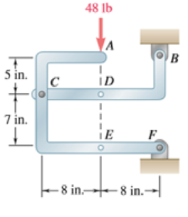
The 48-lb load is removed and a 288-lb · in. clockwise couple is applied successively at A, D, and E. Determine the components of the reactions at Band F if the couple is applied (a) at A, (b) at D, (c) at E.
(a)
The component of reactions at point B and F when the couple is applied at A.
Answer to Problem 6.89P
The x component of the reaction force at point B is
The x component of force applied is
Explanation of Solution
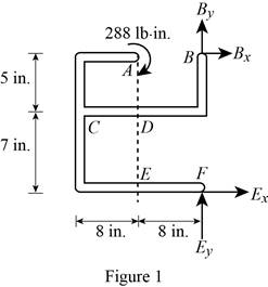
The free body diagram of the problem 6.89P is shown in figure 1 below.
A clockwise couple is applied at A,D, and E. Due to this couple, resultant reaction forces are experienced in points A, D, and E.
First consider the couple applied at point A.
Write the equation to find the sum of moments of force at point F.
Here,
Since the sum of moments of force at a point of a system in equilibrium is zero, rewrite the equation for the sum of moments.
Write the equation to find the x components of force.
Here,
Since the sum of forces at a point is zero in equilibrium, the above equation is rewritten.
Substitute
Write the equation to find the sum of y component of forces.
Here,
No force is applied in the y direction, therefore there will be no reaction also.
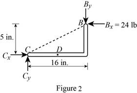
Consider figure 2.
Write the equation to find the y component of reaction force at point B.
Here,
Rewrite equation (I) to find the value of
Conclusion:
Observe figure 2.
Substitute
The y component of reaction force at point B is having a magnitude of
Substitute
The y component of the force applied at point b is
Therefore, the x component of the reaction force at point B is
The x component of force applied is
(b)
The component of reactions at point B and F when the couple is applied at D.
Answer to Problem 6.89P
The x component of the reaction force at point B is
The x component of force applied is
Explanation of Solution
The free body diagram of the problem 6.89P is shown in figure 1.
A clockwise couple is applied at A,D, and E. Due to this couple, resultant reaction forces are experienced in points A, D, and E.
Consider the couple applied at point D.
Write the equation to find the sum of moments of force at point F.
Here,
Since the sum of moments of force at a point of a system in equilibrium is zero, rewrite the equation for the sum of moments.
Write the equation to find the x components of force.
Here,
Since the sum of forces at a point is zero in equilibrium, the above equation is rewritten.
Substitute
Write the equation to find the sum of y component of forces.
Here,
No force is applied in the y direction, therefore there will be no reaction also.
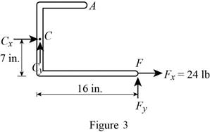
Consider figure 3.
Write the equation to find the y component of reaction force at point B.
Here,
Rewrite equation (I) to find the value of
Conclusion:
Observe figure 3.
Substitute
The y component of force at point B is having a magnitude of
Substitute
The y component of the reaction force applied at point B is
Therefore, the x component of the reaction force at point B is
The x component of force applied is
(c)
The component of reactions at point B and F when the couple is applied at E.
Answer to Problem 6.89P
The x component of the reaction force at point B is
The x component of force applied is
Explanation of Solution
The free body diagram of the problem 6.89P is shown in figure 1.
A clockwise couple is applied at A,D, and E. Due to this couple, resultant reaction forces are experienced in points A, D, and E.
First consider the couple applied at point E.
Write the equation to find the sum of moments of force at point F.
Here,
Since the sum of moments of force at a point of a system in equilibrium is zero, rewrite the equation for the sum of moments.
Write the equation to find the x components of force.
Here,
Since the sum of forces at a point is zero in equilibrium, the above equation is rewritten.
Substitute
Write the equation to find the sum of y component of forces.
Here,
No force is applied in the y direction, therefore there will be no reaction also.
Consider figure 4.
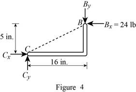
Write the equation to find the y component of reaction force at point B.
Here,
Rewrite equation (VII) to find the value of
Conclusion:
Observe figure 4.
Substitute
The y component of reaction force at point B is having a magnitude of
Substitute
The y component of the force applied at point b is
Therefore, the x component of the reaction force at point B is
The x component of force applied is
Want to see more full solutions like this?
Chapter 6 Solutions
VECTOR MECHANICS FOR ENGINEERS: STATICS


- My ID#016948724 please solve this problems and show me every step clear to follow pleasearrow_forwardMy ID# 016948724arrow_forwardPlease do not use any AI tools to solve this question. I need a fully manual, step-by-step solution with clear explanations, as if it were done by a human tutor. No AI-generated responses, please.arrow_forward
- Please do not use any AI tools to solve this question. I need a fully manual, step-by-step solution with clear explanations, as if it were done by a human tutor. No AI-generated responses, please.arrow_forwardPlease do not use any AI tools to solve this question. I need a fully manual, step-by-step solution with clear explanations, as if it were done by a human tutor. No AI-generated responses, please.arrow_forward[Q2]: The cost information supplied by the cost accountant is as follows:Sales 20,00 units, $ 10 per unitCalculate the (a/ newsale guantity and (b) new selling price to earn the sameVariable cost $ 6 per unit, Fixed Cost $ 30,000, Profit $ 50,000profit ifi) Variable cost increases by $ 2 per unitil) Fixed cost increase by $ 10,000Ili) Variable cost increase by $ 1 per unit and fixed cost reduces by $ 10,000arrow_forward
- can you please help me perform Visual Inspection and Fractography of the attatched image: Preliminary examination to identify the fracture origin, suspected fatigue striation, and corrosion evidences.arrow_forwardcan you please help[ me conduct Causal Analysis (FTA) on the scenario attatched: FTA diagram which is a fault tree analysis diagram will be used to gain an overview of the entire path of failure from root cause to the top event (i.e., the swing’s detachment) and to identify interactions between misuse, material decay and inspection errors.arrow_forwardhi can you please help me in finding the stress intensity factor using a k-calcluator for the scenario attathced in the images.arrow_forward
 International Edition---engineering Mechanics: St...Mechanical EngineeringISBN:9781305501607Author:Andrew Pytel And Jaan KiusalaasPublisher:CENGAGE L