
Concept explainers
Videos
The force in each of the members of the truss for the given loading.
Answer to Problem 6.38P
The force in member
Explanation of Solution
The free-body diagram of the entire truss is shown in figure 1.
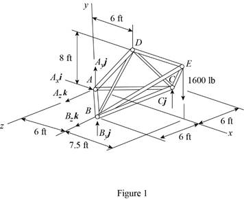
Refer to figure 1 and use symmetry.
Here,
The
Here,
Sum of the moments must be equal to zero.
Here,
Write the equation for
Here,
Put the above equation in equation (I).
Write the expression for the reaction at the point A.
Here,
Substitute
Use symmetry.
Here,
The
Here,
Write the expression for
Put the above equation in equation (II).
Write the expression for the reaction at the point A.
Here,
Substitute
Consider the free body
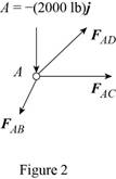
The net force must be equal to zero.
Here,
Write the expression for
Put the above equation in equation (III).
Here,
Write the expression for
Here,
Write the expression for
Here,
Write the expression for
Here,
Put equations (V), (VI) and (VII) in equation (IV).
Factorize
Equate the coefficient of
Equate the coefficient of
Equate the coefficient of
Put equation (X) in equation (IX).
Substitute
Put the above equation in equation (X).
Consider the free-body joint B. The free-body diagram of joint B is shown in figure 3.
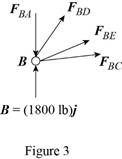
Refer to figure (3) and write the expression for the forces.
Here,
Substitute
Write the expression for
Here,
Write the expression for
Here,
Write the expression for
Here,
Substitute
Write the expression for
Put the above equation in equation (III).
Put equations (XI), (XII), (XIII) , (XIV) and substitute
Equate the coefficient of
Equate the coefficient of
Substitute
Equate the coefficient of
Substitute
Use symmetry.
Here,
Substitute
Consider the free body joint D. The free body diagram is shown in figure 4.
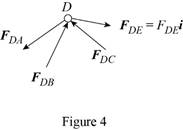
Write the expression for
Put the above equation in equation (III).
Only
Equate the coefficient of
Substitute
Conclusion:
Thus, the force in member
Want to see more full solutions like this?
Chapter 6 Solutions
VECTOR MECHANICS FOR ENGINEERS: STATICS


- Water flows in a 2-ft-wide rectangular channel at a rate of 10 ft³/s. If the water depth downstream of a hydraulic jump is 2.5 ft, determine (a) the water depth upstream of the jump, (b) the upstream and (c) downstream Froude numbers, and (d) the head loss across the jump. (a) y₁ = i (b) Fr₁ = i (c) Fr₂ = i (d) h₁ = ft ftarrow_forwardA hydraulic jump at the base of a spillway of a dam is such that the depths upstream and downstream of the jump are 0.8 and 3.2 m, respectively (see the Video). If the spillway is 12 m wide, what is the flowrate over the spillway? Q= i m³/sarrow_forward(Manning equation) Water flows in a rectangular channel of width b at a depth of b/2. Determine the diameter of a circular channel (in terms of b) that carries the same flowrate when it is half-full. Both channels have the same Manning coefficient, n, and slope. barrow_forward
- (Manning equation) A weedy irrigation canal of trapezoidal cross section is to carry 20 m³/s when built on a slope of 0.60 m/km. If the sides are at a 45° angle and the bottom is 8 m wide, determine the width of the waterline at the free surface. i marrow_forwardWater flows in a 1.2-m-diameter finished concrete pipe so that it is completely full and the pressure is constant all along the pipe. If the slope is So = 0.0073, (a) determine the flowrate by using open-channel flow methods. Compare this result with (b) that obtained using the pipe flow methods of Chapter 8 (Use Colebrook formula, Table 8.1, Table 10.1 and assume that Re > 10º). (a) Q = i (b) Q = i m³/s m³/sarrow_forwardfor this 4 figuredarw the Kinematic Diagram:DoF:F=Type/Name ofmechanismEvolution:arrow_forward
- Two channels and two plates are used to formthe column section shown. For b = 200 mm,determine the moments of inertia and theradii of gyration of the combined section withrespect to the centroidal x and y axes.For the section of problem, determine thefirst moment of the upper plate about thecentroidal x-axisarrow_forwardDetermine by direct integration the moment of inertia of theshaded area at right with respect to the x axis shown. Determine by direct integration the moment of inertia of theshaded area of the figure with respect to the y axis shown.arrow_forwardFor the following MATLAB code, I need to answer a few questions. Can you identify the curves as elliptic functions? Which curves reflect the sn, cn, and dn functions?From the curves, determine the maximum amplitudes and the period corresponding toeach angular velocity component. clc; clear all; I = [500; 125; 425]; w = [0.2; 0.1; 0.2]; rev = 0:0.01:10; C = eye(3); % Using ode45 to integrate the KDE and DDE options = odeset('RelTol',1e-9,'AbsTol',1e-9); result = ode45(@K_DDE, rev, [w; I; C(:)], options); v = result.x; % Extracting information from the ode45 solver w = result.y(1:3, :); C_ode = reshape(result.y(7:end, :), [3,3,length(v)]); plot(v, w) xlabel('rev') ylabel('w (rad/s)') legend('w1', 'w2', 'w3') % Functions function dwCdt = K_DDE(~, w_IC) % Extracting the initial condtions to a variable w = w_IC(1:3); I = w_IC(4:6); C = reshape(w_IC(7:end), [3, 3]); I1 = I(1); I2 = I(2); I3 = I(3); K1 = -(I3-I2)/I1; K2 = -(I1-I3)/I2; K3 = -(I2-I1)/I3; %…arrow_forward
- please show a drawing/image and explain how to properly do the question. thanksarrow_forwardFor the four-bar- linkage shown in the following figure. BC=68mm, CD=100mm, AD=120mm. Determine the range of AB to make it a crank-rocker mechanism. B Darrow_forwardall of those 4 fi 1)Draw kinematic diagram: 2)DOF: 3)type/name of mechanism 4)evolution:arrow_forward
 International Edition---engineering Mechanics: St...Mechanical EngineeringISBN:9781305501607Author:Andrew Pytel And Jaan KiusalaasPublisher:CENGAGE L