Concept explainers
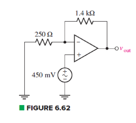
For the circuit of Fig. 6.62, calculate the differential input voltage and the input bias current if the op amp is a(n) (a) μA741; (b) LF411; (c) AD549K.

(a)
Find the differential input voltage and input bias current of op amp.
Answer to Problem 50E
The differential voltage
Explanation of Solution
Given Data:
Differential op amp is
Calculation:
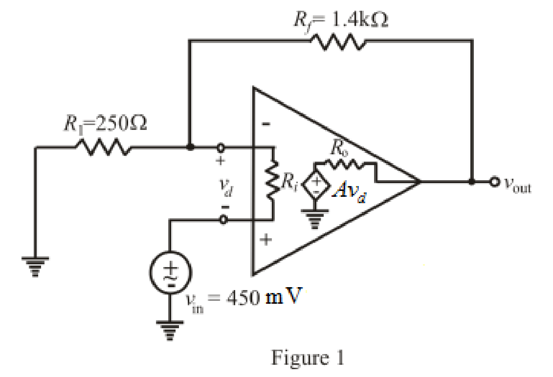
The redrawn circuit of op amp is shown in Figure 1 as follows:

Refer to the redrawn Figure 1:
The expression for the nodal analysis at the nodal voltage
Here,
The expression for nodal analysis at nodal voltage
Here,
The expression for the bias input current of differential op amp is:
Here,
Simplify the equation (1) for
Refer to the TABLE 6.3 in the textbook.
Substitute
Rearrange for
Substitute
Substitute
Substitute
Rearrange for
Conclusion:
Thus, the differential voltage
(b)
Find the differential input voltage and input bias current of op amp.
Answer to Problem 50E
The differential voltage
Explanation of Solution
Given Data:
Differential op amp is
Calculation:
Refer to the TABLE 6.3 in the textbook.
Substitute
Rearrange for
Substitute
Substitute
Substitute
Rearrange for
Conclusion:
Thus, the differential voltage
(c)
Find the differential input voltage and input bias current of
Answer to Problem 50E
The differential voltage
Explanation of Solution
Given Data:
Differential op amp is
Calculation:
Refer to the TABLE 6.3 in the textbook.
Substitute
Rearrange for
Substitute
Substitute
Substitute
Rearrange for
Conclusion:
Thus, the differential voltage
Want to see more full solutions like this?
Chapter 6 Solutions
Engineering Circuit Analysis
Additional Engineering Textbook Solutions
Starting Out with Java: From Control Structures through Objects (7th Edition) (What's New in Computer Science)
BASIC BIOMECHANICS
Database Concepts (8th Edition)
Electric Circuits. (11th Edition)
Concepts Of Programming Languages
Thermodynamics: An Engineering Approach
- 1- Find the Laplace transform and the corresponding ROC of the following signals. a) x(t) = [et + et cos(3t)]u(t) b)x(t) = e-alte-atu(t) + eatu(-t), consider a>0. c) x(t)=8(t) +8(t-1)+8(t−2) d) x(t) = u(-1)-u(1) e) x(t) = e-³t sin(2t)u(t)dr f)x(t) =[r³ +sin(2t)]u(t)dt g)x(t)=t2e2 cos(5t) u(t - 1)arrow_forwardThe transfer function of causal LTI system is H(s) = s+1 (s+1)(s+3) Determine the response y(t) when the input x(t) = elt, for the following region of convergence :) Re[s]> -3 ii) Re[s]Re[s]> -3arrow_forwardConsider the signal y(t) = x₁(t-2) x2(-t + 3) where x₁(t) = e−2tu(t) and x2(t) = eu(t). Determine the Laplace transform of y(t) using the properties. Also find the ROC.arrow_forward
- Consider the LTI system with the input x(t) = eu(t) and the impulse response h(t) = e−2tu(t). a) Determine the Laplace transform of x(t) and h(t). b) Using convolutional property, determine the Laplace transform of the output y(t). Find the ROC for each case.arrow_forward2) a) Plot the voltage transfer characteristic of the circuit below. Assume diode and zener are ideal with VDon=0V (20Pts) view 1K 1, B-100, VBE =0,7V ovo VCEsat = 0V, 2K It 10 V 8V zenerarrow_forwardcircuit dchow find vth step by step rth find RL that enables the circuit to deliver maximum power to terminal then plot norton cırcuitarrow_forward
- Don't use ai to answer I will report you answerarrow_forwardSA [(a) 5 V (b) 5 V] 13. Find the voltage V in the network shown in Fig. 2.44 (a) if R is 10 2 and (b) 20 2 14. In the network of Fig. 2.44 (b), calculate the voltage between points a and b i.e. Vab [30 V] (Elect. Engg. I, Bombay Univ.) 4A 78A 4 h 10A ww 3A (a) ΤΑ 6A DC Network Theorems SA Is 1A 77 12A www 12 6A 8A Fig. 2.44 (b) [Hint: In the above two cases, the two closed loops are independent and no current passes between them].arrow_forwardNeed a solarrow_forward
 Introductory Circuit Analysis (13th Edition)Electrical EngineeringISBN:9780133923605Author:Robert L. BoylestadPublisher:PEARSON
 Delmar's Standard Textbook Of ElectricityElectrical EngineeringISBN:9781337900348Author:Stephen L. HermanPublisher:Cengage Learning
 Programmable Logic ControllersElectrical EngineeringISBN:9780073373843Author:Frank D. PetruzellaPublisher:McGraw-Hill Education
 Fundamentals of Electric CircuitsElectrical EngineeringISBN:9780078028229Author:Charles K Alexander, Matthew SadikuPublisher:McGraw-Hill Education
 Electric Circuits. (11th Edition)Electrical EngineeringISBN:9780134746968Author:James W. Nilsson, Susan RiedelPublisher:PEARSON
 Engineering ElectromagneticsElectrical EngineeringISBN:9780078028151Author:Hayt, William H. (william Hart), Jr, BUCK, John A.Publisher:Mcgraw-hill Education,


