Concept explainers
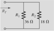
Find the total resistance for each configuration in Fig. 6.6. Note that only standard value resistors were used.

Trending nowThis is a popular solution!
Learn your wayIncludes step-by-step video

Chapter 6 Solutions
Introductory Circuit Analysis; Laboratory Manual For Introductory Circuit Analysis Format: Kit/package/shrinkwrap
Additional Engineering Textbook Solutions
Starting Out with C++: Early Objects (9th Edition)
Thinking Like an Engineer: An Active Learning Approach (4th Edition)
Introduction To Programming Using Visual Basic (11th Edition)
Starting Out with Java: From Control Structures through Objects (7th Edition) (What's New in Computer Science)
Starting Out with Programming Logic and Design (5th Edition) (What's New in Computer Science)
Computer Science: An Overview (13th Edition) (What's New in Computer Science)
- Only expert should solve itarrow_forwardWhat is the high cutoff frequency? What is the low cutoff frequency? What is the bandwidth?arrow_forwardNeed handwritten pen and paper solution do not use chatgpt or AI otherwise downvote. An AC motor with impedance Z₁ = 4.2 + j3.6 ohm is supplied from a source of 220 V at 60 Hz. Find: a) pf, P and Q, b) Determine the capacitor required to connect in parallel with the motor so that the power factor is corrected and equal to 0.98 behind.arrow_forward
- Need handwritten pen and paper solution do not use chatgpt or AI otherwise downvote An AC motor with impedance Z₁ = 4.2 + j3.6 ohm is supplied from a source of 220 V at 60 Hz. Find: a) pf, P and Q, b) Determine the capacitor required to connect in parallel with the motor so that the power factor is corrected and equal to 0.98 behind.arrow_forwardFind;- magnitude of line voltages Line currents Verify that th eload is balanced, i.e In = 0arrow_forwardDon't use ai to answer I will report you answerarrow_forward
- Don't use ai to answer I will report you answerarrow_forward(b) Below is a FSM with a 1-bit input A, and a 1-bit output Y. Deter- mine the combined state and output table. Identify the unreachable states, and sketch the state-transition diagram. In your table and diagram, use Os and 1s for the states and next states, not symbols like S0, S1, etc. A D D D CLK S'₁₂ S2 S₁₁ S1 Y S' r So S2 S₁ So resetarrow_forwardDo by pen and paper not using chatgpt Determine the output current of E1 in the circuit shown in . The voltage drop of the diodes is 0.7 V.arrow_forward
- Don't use ai to answer I will report you answerarrow_forwardFor the amplifier shown, if β = 150: Calculate the input impedance at the base. Calculate the input impedance of the stage.arrow_forward53. Obtain an expression for i(t) as labeled in the circuit diagram of Fig. 8.84, and determine the power being dissipated in the 40 2 resistor at t = 2.5 ms. t=0 i(t) 30 Ω w 200 mA 4002 30 m 100 mA(arrow_forward
 Introductory Circuit Analysis (13th Edition)Electrical EngineeringISBN:9780133923605Author:Robert L. BoylestadPublisher:PEARSON
 Delmar's Standard Textbook Of ElectricityElectrical EngineeringISBN:9781337900348Author:Stephen L. HermanPublisher:Cengage Learning
 Programmable Logic ControllersElectrical EngineeringISBN:9780073373843Author:Frank D. PetruzellaPublisher:McGraw-Hill Education
 Fundamentals of Electric CircuitsElectrical EngineeringISBN:9780078028229Author:Charles K Alexander, Matthew SadikuPublisher:McGraw-Hill Education
 Electric Circuits. (11th Edition)Electrical EngineeringISBN:9780134746968Author:James W. Nilsson, Susan RiedelPublisher:PEARSON
 Engineering ElectromagneticsElectrical EngineeringISBN:9780078028151Author:Hayt, William H. (william Hart), Jr, BUCK, John A.Publisher:Mcgraw-hill Education,


