
EBK PRINCIPLES OF ELECTRIC CIRCUITS
10th Edition
ISBN: 9780134880068
Author: Buchla
Publisher: VST
expand_more
expand_more
format_list_bulleted
Concept explainers
Videos
Textbook Question
Chapter 6, Problem 21RP
The amplifier in one channel of a stereo system as shown in Figure 6-41 drives two speakers. If the maximum voltage to the speakers is 15 V, how much power must the amplifier be able to deliver to the speakers?
FIGURE 6-41
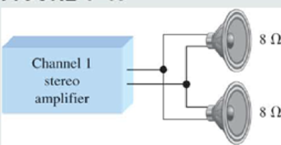
If the amplifier can produce a maximum of 18 V, what is the maximum total power to the speakers?
Expert Solution & Answer
Want to see the full answer?
Check out a sample textbook solution
Students have asked these similar questions
6) For each independent source in this circuit calculate
the amount of power being supplied or the amount of
power being absorbed
+
6V
www
+3V-
www
20
ми
ми
352
0.5A
+
3V
In this experiment, we are going to use a 2N3904 BJT. Examine the data sheet for this device
carefully. In particular, make a note of the current gain (identified by hFE).
1. Obtain the curve trace for a "Darlington Pair" of Bipolar Junction Transistors. A Darlington
Pair consists of two transistors with the first BJT driving the base terminal of the second
transistor as shown in Figure 1 below.
A. Set up the primary sweep voltages for V1 the same as shown in the lecture notes (see
the Darlington pair IV curve).
B. Set up the secondary sweep currents for 11 to be an order of magnitude smaller than
for the single BJT. In the Sweep Type box choose linear and enter the following 3
values: Start Value: 0, End Value: 8u and Increment: 1u (see lecture notes).
C. Describe the primary differences you observe between the single BJT Curve Trace and
that of the Darlington Pair. Discuss what might cause each difference.
Q1
11
Q2
V1
Q2N3904
Figure 1. A Darlington Pair of 2N3904 transistors in a…
2. Using the IV plots shown in Fig. 3 (and found in the reintroduction to PSpice) design a BJT
biasing circuit that results in the following parameters: VCE = 2 Vand ig = 40 μA. We
also require the power supply to be fixed at 5 Volts (this is where the load line intercepts
the iB =ic = 0 line). You may use the circuit shown in Example 1. Note that all resistor
values in Example 1 must be recalculated. Your solution for the base to ground and base
to collector resistors may not be unique.
Chapter 6 Solutions
EBK PRINCIPLES OF ELECTRIC CIRCUITS
Ch. 6 - Five resistors are positioned on a protoboard as...Ch. 6 - How would you connect all of the resistors in...Ch. 6 - If a third branch is added to the circuit in...Ch. 6 - Determine IT and I2 if a fourth branch is added to...Ch. 6 - How much current will an ammeter measure when it...Ch. 6 - When the brake lights are applied, the total...Ch. 6 - If a 33 resistor is connected in parallel in...Ch. 6 - Calculate the total resistance connected to the...Ch. 6 - If two of the speakers are removed, what is the...Ch. 6 - The basic circuit for a rear window defroster can...
Ch. 6 - If you need to obtain a total resistance of 130 ,...Ch. 6 - Sometimes a direct measurement of resistance is...Ch. 6 - Determine the current through RL in Figure 6-0...Ch. 6 - Figure 6-35 Determine the current through each...Ch. 6 - Determine the total amount of power in the...Ch. 6 - The amplifier in one channel of a stereo system as...Ch. 6 - In Figure 6-51, there is a total current of 31.09...Ch. 6 - Your ohmmeter indicates 9.6 k between pin 2 and...Ch. 6 - A 330 resistor, a 270 resistor, and a 68 ...Ch. 6 - Refer to Figure 6-83 If R7 opens, the resistance...Ch. 6 - Determine whether or not all the resistors in...Ch. 6 - The following currents are measured in the same...Ch. 6 - There is a total of 500 mA of current into five...Ch. 6 - In the circuit of Figure 6-65, determine the...Ch. 6 - The electrical circuit in a room has a ceiling...Ch. 6 - The following resistors are connected in parallel:...Ch. 6 - What is the total current in each circuit of...Ch. 6 - Find the values of the unspecified quantities...Ch. 6 - What is the current through each resistor in...Ch. 6 - Determine all of the resistor values in Figure...
Knowledge Booster


Learn more about
Need a deep-dive on the concept behind this application? Look no further. Learn more about this topic, electrical-engineering and related others by exploring similar questions and additional content below.Similar questions
- A circuit is given as shown. (a) Find and label the circuit nodes. (6) Determine I, I₁, I2 and V₂ I₂ +1 I 12V ww 22 2 ти + 보통 162 - ти 4 52 12 50 602 I 1 Mwarrow_forwarda) A silicon wafer is uniformly doped p-type with NA=10¹³/cm³. At T=0K, what are the equilibrium hole and electron concentrations?arrow_forward1016 1015 Ge 101 Si 1013 1012 GaAs 10" (( uວ) uot¤ງແລ້ວuo ວາ.ຂ ວາsuuuT 0101 601 801 107 10% Determine the equilibrium electron and hole concentrations inside a uniformly doped sample of Si under the following conditions. (n; =1010/cm³ at 300K) a) T 300 K, NA << ND, ND = 1015/cm³ b) T 300 K, NA = 9X10¹⁵/cm³, ND = 1016/cm³ c) T = 450 K, NA = 0, ND = 1014/cm³ d) T = 650 K, NA = 0, ND = 1014/cm³ 10° 200 300 400 500 600 700 T(K)arrow_forward
- b) A semiconductor is doped with an impurity concentration N such that N >> n; and all the impurities are ionized. Also, n = N and p = n2/N. Is the impurity a donor or an acceptor? Explain.arrow_forwardd) For a silicon sample maintained at T=300K, the Fermi level is located 0.259 eV above the intrinsic Fermi level. What are the hole and electron concentrations?arrow_forwarde) In a nondegenerate germanium sample maintained under equilibrium conditions near room temperature, it is known that n=10¹³/cm³, n = 2p, and NA 0. Determine n and ND.arrow_forward
- Solve fo the voltage across the 1kohm resistor using superposition for the three following cases: only V1 present, only V2 present, and both V1 and V2 present.arrow_forwardSemiconductor A has a band gap of 1eV, while semiconductor B has a band gap of 2eV. What is the ration of the intrinsic carrier concentrations in the two materials (n₁A/NB) at 300 K. Assume any differences in the carrier effective masses may be neglected.arrow_forwardc) The electron concentration in a piece of Si maintained at 300K under equilibrium conditions is 105/cm³. What is the hole concentration?arrow_forward
- 5. Represent the following system in state-space form. Write A, B, C and D clearly in your answer. d³y d²y dt3 - +5y=2u dt²arrow_forward3. Find the transfer function H(s) and frequency response H (w) of the following system whose differential equation is given by d¹y d³y +3. dy +5 dt4 dt3 dt - d²u du 4y = - 5 dt² dtarrow_forward1. Consider a plant that you want to control. The input u(t) and output y(t) of the plant are related by y(t) = 7 u(t) + w(t) where w(t) is an additive disturbance at the output which is bounded by -0.5 w(t) ≤0.5 for all time t. You want to build a controller so that the output follows a constant reference signal r(t) = where -15 ≤≤ 15. You will consider both open-loop and closed-loop for this problem. a) Sketch the block diagram of the plant. b) Please build an open-loop controller that sets the output to 7, assuming the disturbance is ignored. Please show your controller both as an equation and a block diagram. c) Say that you use the open-loop controller in part b, but now the disturbance w(t) is present. What is the maximum possible magnitude of error in the output for the reference signal? Suppose you have designed a feedback control for the plant where the controller has the form u(t) = K(r(t) − y(t)). Here K is the gain constant of the controller that you will design. d) Please…arrow_forward
arrow_back_ios
SEE MORE QUESTIONS
arrow_forward_ios
Recommended textbooks for you
 Electricity for Refrigeration, Heating, and Air C...Mechanical EngineeringISBN:9781337399128Author:Russell E. SmithPublisher:Cengage Learning
Electricity for Refrigeration, Heating, and Air C...
Mechanical Engineering
ISBN:9781337399128
Author:Russell E. Smith
Publisher:Cengage Learning
What is an electric furnace and how does it work?; Author: Fire & Ice Heating and Air Conditioning Inc;https://www.youtube.com/watch?v=wjAWecPGi0M;License: Standard Youtube License