
Videos
For the op amp circuit shown in Fig. 6.39, calculate vout if (a) R1 = R2 = 100 Ω, and vin = 5 V; (b) R2 = 200R1 and vin = 1 V; (c) R1 = 4.7 kΩ, R2 = 47 kΩ, and vin = 20 sin 5t V.
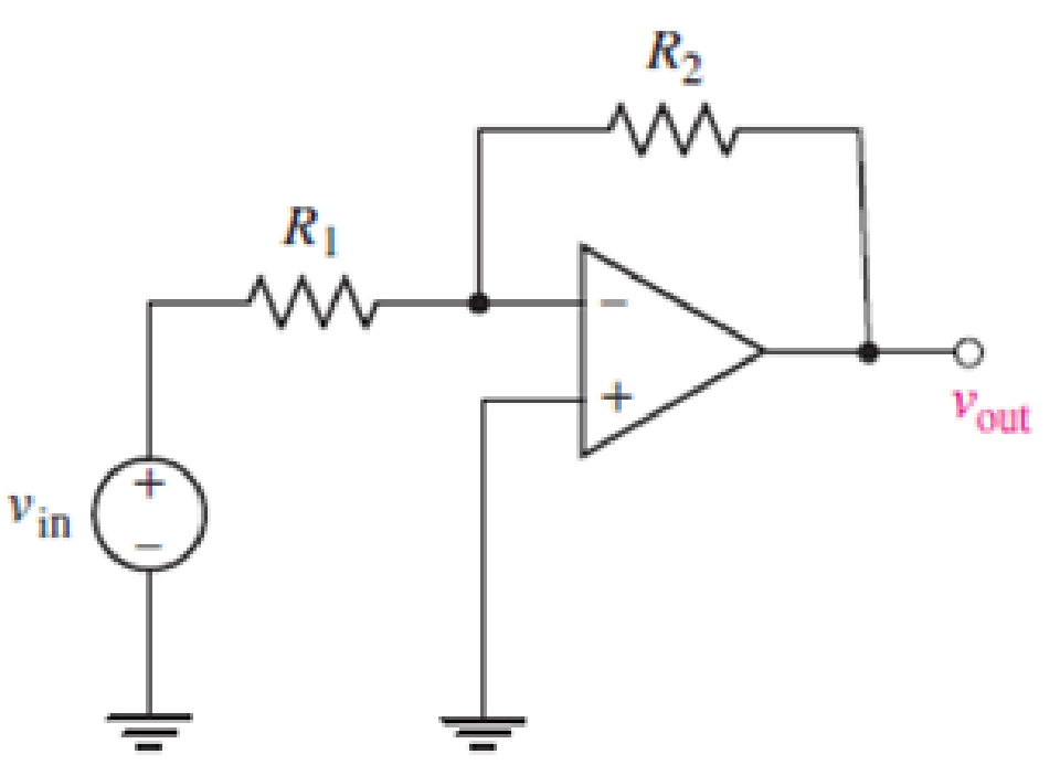
FIGURE 6.39
(a)
Find the value of
Answer to Problem 1E
The value of
Explanation of Solution
Formula used:
Refer to the FIGURE 6.39 in the Textbook.
The expression for the relation of
Here,
Calculation:
Refer to the FIGURE 6.39 in the Textbook.
Substitute
Conclusion:
Thus, the value of
(b)
Find the value of
Answer to Problem 1E
The value of
Explanation of Solution
Calculation:
Refer to the FIGURE 6.39 in the Textbook.
Substitute
Conclusion:
Thus, the value of
(c)
Find the value of
Answer to Problem 1E
The value of
Explanation of Solution
Calculation:
Refer to the FIGURE 6.39 in the TEXTBOOK.
Substitute
Conclusion:
Thus, the value of
Want to see more full solutions like this?
Chapter 6 Solutions
Loose Leaf for Engineering Circuit Analysis Format: Loose-leaf


- 9-1) Lathi & Ding, Prob. P.5.1-10 (a) A first-order-hold circuit can also be used to reconstruct a signal g(t) from its samples. The impulse response of this circuit is h(t) = A ( 2Ts 12 where Ts is the sampling interval. Consider a typical sampled signal ğ(t) and show that this circuit performs the linear interpolation. In other words, the filter output consists of sample tops connected by straight-line segments. Follow the procedure discussed in Sec. 5.1.2 (Fig. 5.6) for a typical signal g(t). (b) Determine the transfer function of this filter and its amplitude response, and compare it with the ideal filter required for signal reconstruction.arrow_forwardI have this rough circuit diagram of a 2 double end trolley light system with a 120 dcv power supply. I would like to know in what way is better to connect the interior lights along with the headlight and door light. Provide the circuit diagram and with its respect connection and the estimated total power rated for the lights. Where: Headlights (2) = #1 and #6Door lights (4) = #2, #4, #5, and #7Platform lights (2) = #3 and #8Interior lights are approximately 20 in quantity. Also, can you say if the components that are in series with the power supply are correct or does it need to be replaced with something else or if it is missing any components.arrow_forwardA domestic load of 2300 kW at 0.88 p.f lagging and a motors load of 3400 kW at 0.85 p.f lagging are supplied by two alternators operating in parallel. If one alternator is delivering a load of 3300 kW at 0.9 p.f lagging, what will be the output power and p.f of the other alternator?arrow_forward
- 9-3) similar to Lathi & Ding, Prob. P.5.2-3 In a satellite radio system, 200 stereo stations are to be packaged in one data stream. For each station, two (left & right) signals of bandwidth 22 kHz are sampled, quantized, and binary-coded into PCM signals. The transmitter then multiplexes the data from the 200 stations into a single stream via TDM and modulates that stream onto a radio carrier using DSB-SC-AM. (a) If the maximum acceptable quantization error is 0.25% of the peak signal voltage, find the minimum number of bits needed for a uniform quantizer. (b) If the sampling rate must be 25% higher than the Nyquist rate, find the minimum bit rate of the multiplexed data stream, based on the quantizer of part (a). (c) If 10% more bits are added for error correction and framing, determine the minimum bandwidth of the radio signal sent to the ground receivers.arrow_forward9-2) similar to Lathi & Ding, Prob. P.5.2-1 A compact disc (CD) records audio signals digitally by using PCM. Assume that the audio signal bandwidth equals 15 kHz. (a) If the Nyquist samples are uniformly quantized into L = 65, 536 levels and then binary-coded, determine the number of binary digits required to encode a sample. (b) if the audio signal has a peak voltage of ±1V and an average signal power of 0.1 V2, find the resulting ratio of signal to quantization noise (SQNR) for the system. (c) Determine the number of binary digits per second (bit/s) required to encode the audio signal. (d) For practical reasons discussed in the text, signals are sampled at a rate well above the Nyquist rate. Practical CDs use 44,100 samples per second. If L = 65,536, determine the number of bits per second required to encode the signal and the minimum bandwidth required to transmit the encoded signal.arrow_forward12.1 Evaluate each of the following integrals: (a) G₁ =√(31³ −4t²+3)[8(t) +28(t − 2)] dt. (b) G2=2(e³t +1)[8(t) −28(t − 2)] dt. 16 (c) G3 = √124t sin(2лt) − 1][§(t − 1)+8(t −6)] dt.|arrow_forward
- 12.3 Express each of the waveforms in Fig. P12.3 (on page667) in terms of step functions and then determine its Laplacetransform. [Recall that the ramp function is related to thestep function by r(t − T) = (t − T) u(t − T).] Assume that allwaveforms are zero for t < 0.arrow_forwardCalculate the torque developed by the motor if Field. excitation is so adjusted as to make the back e.mif twice the applied voltage and α = 16°, Neglecting losses for a 3-phasi 150 KW 2300 V, 50 Hz, 1000 rpm salient Pole synchronous motor has Xd=32 52/Phase and Xy = 2052/phase. 7arrow_forwardASSIGNMENT NO. 6 1. Consider the circuit below with C = 0.02 uF, Ri 100 kr and Rf = 470 k2. The input waveform has T = 0.5 ms and Vp = 8 V. Under steady state conditions, determine the peak-to-peak value of the output voltage.arrow_forward
- An RLC circuit is build with a 250 microfarad capacitor 10 mH inductor an a 15 ohms resistance in series. It isoperated with a Voltage source of Frequency of 400HZ and maximum voltage 12V. Find the angular frequency of thesource. Find the reactance of each circuit element. Find the impedance and the peak current. Find the phase factortheta between the current and the voltage source. Write the current and voltage of the circuit as a function of time.Draw an approximate V vs t and I vs t diagram. Find the resonance frequencyarrow_forwardThe project conditions are:The project functionality will be provided as per the project description suppliedbelow.You must present/demonstrate the project as a group, at the given time,andwithin a given time limit ( 20 mins ).A soft copy of all project documents is required before you The program functionality should be as follows:• Upon entering the “run” mode all counters/timers must be reset (use the first scan bit).• When students scan RFID cards, the opening motor automatically opens the door and closing motor closes it after a 5 second wait.• The current number of students should be counted by incrementing/decrementing as students enter or leave the classroom. • The number of students entering the classroom is counted using a reflective sensor, while the number leaving is counted using a fiber optic sensor. The count should be displayed in the decimal tag "Total no of students”.• The maximum number of students in the classroom is 20, and when the classroom is occupied by the…arrow_forwardSolve this problem and show all of the workarrow_forward
 Delmar's Standard Textbook Of ElectricityElectrical EngineeringISBN:9781337900348Author:Stephen L. HermanPublisher:Cengage Learning