
Fundamentals of Applied Electromagnetics (7th Edition)
7th Edition
ISBN: 9780133356816
Author: Fawwaz T. Ulaby, Umberto Ravaioli
Publisher: PEARSON
expand_more
expand_more
format_list_bulleted
Concept explainers
Videos
Textbook Question
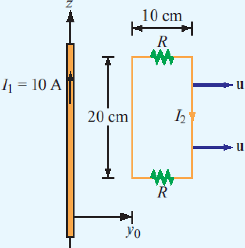
Chapter 6, Problem 11P
The loop shown in P6.11 moves away from a wire carrying a current I1 = 10 A at a constant velocity
Expert Solution & Answer
Want to see the full answer?
Check out a sample textbook solution
Students have asked these similar questions
Help with homework, with the extra portion part too please
Redraw the previous circuit and add a 24 V red lamp to indicate the relay coil is on, a 230 V yellow lamp to indicate the solenoid is on, green lamp to indicate the solenoid is off. Use only one relay, which has multiple contacts.
Design a control circuit so a 24 V relay , start button, and a stop push button (on/off with memory) operates an electromechanical relay to control a 230 V solenoid
Next, Redraw the previous circuit and add a 24 V red lamp to indicate the relay coil is on, a 230 V yellow lamp to indicate the solenoid is on, green lamp to indicate the solenoid is off. Use only one relay, which has multiple contacts.
Chapter 6 Solutions
Fundamentals of Applied Electromagnetics (7th Edition)
Ch. 6.2 - Explain Faradays law and the function of Lenzs...Ch. 6.2 - Prob. 2CQCh. 6.2 - Prob. 3CQCh. 6.2 - For the loop shown in Fig. 6-3, what is Vemftr if...Ch. 6.2 - Suppose that the loop of Example 6-1 is replaced...Ch. 6.4 - Suppose that no friction is involved in sliding...Ch. 6.4 - Is the current flowing in the rod of Fig. 6-10 a...Ch. 6.4 - For the moving loop of Fig. 6-9, find I when the...Ch. 6.4 - Suppose that we turn the loop of Fig. 6-9 so that...Ch. 6.5 - Contrast the operation of an ac motor with that of...
Ch. 6.5 - Prob. 7CQCh. 6.5 - Prob. 8CQCh. 6.7 - A poor conductor is characterized by a...Ch. 6.8 - When conduction current flows through a material,...Ch. 6.8 - Verify that the integral form of Ampres law given...Ch. 6.10 - Explain how the charge continuity equation leads...Ch. 6.10 - How long is the relaxation time constant for...Ch. 6.10 - Determine (a) the relaxation time constant and (b)...Ch. 6.11 - Prob. 7ECh. 6 - The switch in the bottom loop of Fig. P6.1 is...Ch. 6 - The loop in Fig. P6.2 is in the xy plane and B =...Ch. 6 - A coil consists of 100 turns of wire wrapped...Ch. 6 - A stationary conducting loop with an internal...Ch. 6 - A circular-loop TV antenna with 0.02 m2 area is in...Ch. 6 - The square loop shown in Fig. P6.6 is coplanar...Ch. 6 - The rectangular conducting loop shown in Fig. P6.7...Ch. 6 - Prob. 8PCh. 6 - Prob. 9PCh. 6 - A 50 cm long metal rod rotates about the z axis at...Ch. 6 - The loop shown in P6.11 moves away from a wire...Ch. 6 - The electromagnetic generator shown in Fig. 6-12...Ch. 6 - The circular, conducting, disk shown in Fig. P6.13...Ch. 6 - The plates of a parallel-plate capacitor have...Ch. 6 - A coaxial capacitor of length l = 6 cm uses an...Ch. 6 - The parallel-plate capacitor shown in Fig. P6.16...Ch. 6 - In wet soil, characterized by = 102 (S/m), r = 1,...Ch. 6 - An electromagnetic wave propagating in seawater...Ch. 6 - At t = 0, charge density v0 was introduced into...Ch. 6 - If the current density in a conducting medium is...Ch. 6 - Prob. 21PCh. 6 - If we were to characterize how good a material is...Ch. 6 - The electric field of an electromagnetic wave...Ch. 6 - The magnetic field in a dielectric material with ...Ch. 6 - Given an electric field E=xE0sinaycos(tkz), where...Ch. 6 - The electric field radiated by a short dipole...Ch. 6 - A Hertzian dipole is a short conducting wire...Ch. 6 - In free space, the magnetic field is given by...Ch. 6 - The magnetic field in a given dielectric medium is...
Knowledge Booster


Learn more about
Need a deep-dive on the concept behind this application? Look no further. Learn more about this topic, electrical-engineering and related others by exploring similar questions and additional content below.Similar questions
- please answer it handwritten , thanks! will give thumbs uparrow_forwardEXAMPLE 6.3 Suppose the Fourier transform of a pulse is as follows: (1-a) Ть. 2Ть H(f) = < α (To) (-Tof+ 1 +a (1-a) (1+α) ·<|f|≤· 2 2ть 2Ть (1+α) 0, <\f\ 2Ть where 0≤a≤1. Show that this pulse in both time and frequency domains satisfies the Nyquist criterion.arrow_forwardIn matlabarrow_forward
- not use ai pleasearrow_forwardIn matlabarrow_forwardEXAMPLE 4.4 In a binary symmetric communication (BSC) channel, the input bits transmitted over the channel are either 0 or 1 with probabilities p and 1-p, respectively. Due to channel noise, errors are made. As shown in Figure 4.4, the channel is assumed to be symmetric, which means the probability of receiving 1 when 0 is transmitted is the same as the probability of receiving 0 when 1 is transmit- ted. The conditional probabilities of error are assumed to be each e. Determine the average prob- ability of error, also known as the bit error rate, as well as the a posteriori probabilities.arrow_forward
- What is the bandwidth requirement in Hz for baseband binary transmission at 64 kbps, if the roll-off factor is 0.25?arrow_forwardEXAMPLE 6.4 Suppose the roll-off factor is 25% and the bandwidth of a baseband transmission system satisfying the Nyquist criterion is 30 kHz. Determine the bit rate. Solution 1+α 1arrow_forwardEXAMPLE 4.9 In a communication system, the noise level is modeled as a Gaussian random variable with m=0 and ² = 0.0001. Determine P(X > 0.01) and P(-0.04 ≤x≤ 0.05). 3arrow_forward
- Suppose the random variable X is uniformly distributed between 0 and 1 with probability 0.25, takes on the value of 1 with probability p, and is uniformly distributed between 1 and 2 with probability 0.5. Determine p as well as the pdf and cdf of the random variable Xarrow_forwardconstants: A (medium) single phase transmission line 100 km long has the following Resistance/km = 0.25 2; Susceptance/km = 14 × 10 siemen; Reactance/km = 0.8 Receiving end line voltage = 66,000 V Assuming that the total capacitance of the line is localised at the receiving end alone, determine (i) the sending end current (ii) the sending end voltage (iii) regulation and (iv) supply power factor. The line is delivering 15,000 kW at 0.8 power factor lagging. Draw the phasor diagram to illustrate your calculations.arrow_forwardFor the power system given below, the voltage at bus 2 is kept at 1.03 pu. The maximum power can be delivered by G2 is 35 MW. Obtain the load flow solution. Take the base power 100 MVA. V₁ = 1.0520 G₁ 0.02+j0.06 G2 V2=1.03 P2 = 35 MW 0.08+j0.24 SL2 20+j50 MVA SL3 60+j25 MVA 0.06+j0.018arrow_forward
arrow_back_ios
SEE MORE QUESTIONS
arrow_forward_ios
Recommended textbooks for you
 Delmar's Standard Textbook Of ElectricityElectrical EngineeringISBN:9781337900348Author:Stephen L. HermanPublisher:Cengage Learning
Delmar's Standard Textbook Of Electricity
Electrical Engineering
ISBN:9781337900348
Author:Stephen L. Herman
Publisher:Cengage Learning
Electric Charge and Electric Fields; Author: Professor Dave Explains;https://www.youtube.com/watch?v=VFbyDCG_j18;License: Standard Youtube License