
Engineering Mechanics: Statics and Modified Mastering Engineering with eText and Access Card (14th Edition)
14th Edition
ISBN: 9780134229287
Author: Russell C. Hibbeler
Publisher: PEARSON
expand_more
expand_more
format_list_bulleted
Videos
Textbook Question
Chapter 5.7, Problem 7FP
The uniform plate has a weight of 500 lb. Determine the tension in each of the supporting cables.
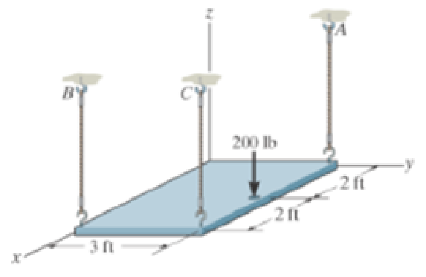
Prob. F5-7
Expert Solution & Answer

Learn your wayIncludes step-by-step video

schedule06:06
Students have asked these similar questions
dny
dn-1y
dn-1u
dn-24
+a1
+
+ Any
=
bi
+b₂-
+ +bnu.
dtn
dtn-1
dtn-1
dtn-2
a) Let be a root of the characteristic equation
1
sn+a1sn-
+
+an
= : 0.
Show that if u(t) = 0, the differential equation has the solution y(t) = e\t.
b) Let к be a zero of the polynomial
b(s) = b₁s-1+b2sn−2+
Show that if the input is u(t)
equation that is identically zero.
=
..
+bn.
ekt, then there is a solution to the differential
B
60 ft
WAB
AB
30%
:
The crane's telescopic boom rotates with the angular velocity w = 0.06 rad/s and
angular acceleration a = 0.07 rad/s². At the same instant, the boom is extending
with a constant speed of 0.8 ft/s, measured relative to the boom. Determine the
magnitude of the acceleration of point B at this instant.
The motion of peg P is constrained by the lemniscate curved
slot in OB and by the slotted arm OA. (Figure 1)
If OA rotates counterclockwise with a constant angular velocity of 0 = 3 rad/s, determine the magnitude of the velocity of peg P at 0 = 30°.
Express your answer to three significant figures and include the appropriate units.
Determine the magnitude of the acceleration of peg P at 0 = 30°.
Express your answer to three significant figures and include the appropriate units.
0
(4 cos 2 0)m²
B
A
Chapter 5 Solutions
Engineering Mechanics: Statics and Modified Mastering Engineering with eText and Access Card (14th Edition)
Ch. 5.2 - Draw the free-body diagram for the following...Ch. 5.2 - Draw the free-body diagram for the following...Ch. 5.2 - Draw the free-body diagram for the following...Ch. 5.2 - Draw the free-body diagram for the following...Ch. 5.2 - Draw the free-body diagram for the following...Ch. 5.2 - Draw the free-body diagram for the following...Ch. 5.2 - Draw the free-body diagram for the following...Ch. 5.2 - Draw the free-body diagram for the following...Ch. 5.2 - Draw the free-body diagram for the following...Ch. 5.4 - Draw the free body diagram of each object. Prob....
Ch. 5.4 - Determine the horizontal and vertical components...Ch. 5.4 - Determine the horizontal and vertical components...Ch. 5.4 - The truss is supported by a pin at A and a roller...Ch. 5.4 - Determine the components of reaction at the fixed...Ch. 5.4 - The 25 kg bar has a center of mass at G. If it is...Ch. 5.4 - Determine the reactions at the smooth contact...Ch. 5.4 - Determine the components of the support reactions...Ch. 5.4 - Determine the reactions at the supports. Prob....Ch. 5.4 - Determine the horizontal and vertical components...Ch. 5.4 - Determine the reactions at the supports. Prob....Ch. 5.4 - Determine the reactions at the supports. Prob....Ch. 5.4 - Determine the reactions at the supports. Prob....Ch. 5.4 - Determine the tension in the cable and the...Ch. 5.4 - The man attempts to a up port the toad of boards...Ch. 5.4 - Determine the components of reaction at the...Ch. 5.4 - The man has a weight W and stands at the center of...Ch. 5.4 - A uniform glass rod having a length L is placed in...Ch. 5.4 - The uniform rod AB has a mass of 40 kg. Determine...Ch. 5.4 - If the intensity of the distributed load acting on...Ch. 5.4 - If the roller at A and the pin at B can support a...Ch. 5.4 - The relay regulates voltage and current. Determine...Ch. 5.4 - Determine the reactions on the bent rod which is...Ch. 5.4 - The mobile crane is symmetrically supported by two...Ch. 5.4 - Determine the reactions acting on the smooth...Ch. 5.4 - A linear torsional spring deforms such that an...Ch. 5.4 - Determine the force P needed to pull the 50-kg...Ch. 5.4 - Determine the magnitude and direction of the...Ch. 5.4 - The operation of the fuel pump for an automobile...Ch. 5.4 - Determine the magnitude of force at the pin A and...Ch. 5.4 - The dimensions of a jib crane, which is...Ch. 5.4 - The dimensions of a jib crane, which is...Ch. 5.4 - The smooth pipe rests against the opening at the...Ch. 5.4 - The beam of negligible weight is supported...Ch. 5.4 - The cantilevered jib crane is used to support the...Ch. 5.4 - The cantilevered jib crane is used to support the...Ch. 5.4 - The bar of negligible weight is supported by two...Ch. 5.4 - Determine the stiffness k of each spring so that...Ch. 5.4 - The bulk head AD Is subjected to both water and...Ch. 5.4 - The boom supports the two vertical loads. Neglect...Ch. 5.4 - The boom is intended to support two vertical loads...Ch. 5.4 - The 10-kg uniform rod is pinned at end A. If It is...Ch. 5.4 - If the truck and its contents have a mass of 50 kg...Ch. 5.4 - Three uniform books each having a weight W and...Ch. 5.4 - Determine the reactions at the pin A and the...Ch. 5.4 - If rope BC will fail when the tension becomes 50...Ch. 5.4 - The rigid metal strip of negligible weight is used...Ch. 5.4 - The rigid metal strip of negligible weight is used...Ch. 5.4 - The cantilever footing is used to support a wail...Ch. 5.4 - The uniform beam has a weight Wand length l and is...Ch. 5.4 - A boy stands out at the end of the diving board,...Ch. 5.4 - The 30-N uniform rod has a length of l = 1 m. If s...Ch. 5.4 - The uniform rod has a length I and weight W. It is...Ch. 5.4 - I he uniform rod of length L and weight W is...Ch. 5.4 - Assuming that the foundation exerts a linearly...Ch. 5.4 - Assuming that the foundation exerts a linearly...Ch. 5.4 - If it is also subjected to a couple moment of 100...Ch. 5.4 - Determine the distance d for placement of the load...Ch. 5.4 - If d = 1 m, and = 30, determine me normal...Ch. 5.4 - The man attempts to pull the tour wheeler up the...Ch. 5.4 - Where is the best place to arrange most of the...Ch. 5.7 - Draw the free-body diagram of each object.Ch. 5.7 - In each case, write the moment equations about the...Ch. 5.7 - The uniform plate has a weight of 500 lb....Ch. 5.7 - Determine the reactions at the roller support A,...Ch. 5.7 - The rod is supported by smooth journal bearings at...Ch. 5.7 - Determine the support reactions at the smooth...Ch. 5.7 - Determine the force developed in the short link...Ch. 5.7 - Determine the components of reaction that the...Ch. 5.7 - Determine the tension each rope and the force that...Ch. 5.7 - If these components have weights WA = 45000 Wa =...Ch. 5.7 - Determine the components of reaction at the fixed...Ch. 5.7 - Determine the vertical reactions at the wheels C...Ch. 5.7 - Determine the components of reaction at A, the...Ch. 5.7 - Determine the tension in each of the three...Ch. 5.7 - Determine the components of reaction at hinges A...Ch. 5.7 - Determine me tension in each cable and the...Ch. 5.7 - The cables are attached to a smooth collar ring at...Ch. 5.7 - Determine the components of reaction at the...Ch. 5.7 - Determine the components of reaction at the...Ch. 5.7 - Determine the components of reaction at the...Ch. 5.7 - Determine the magnitude of F which will cause the...Ch. 5.7 - Determine the components of reaction at A and the...Ch. 5.7 - Determine the components of reaction at these...Ch. 5.7 - Determine the components or reaction at these...Ch. 5.7 - Compute the x, y, z components of reaction at the...Ch. 5.7 - Determine the magnitude of F2 which will cause the...Ch. 5.7 - At A the connection is with a ball-and-socket....Ch. 5.7 - If it is supported by a ball-and-socket joint at C...Ch. 5.7 - Determine the x, y, z components of reaction at...Ch. 5.7 - Determine the horizontal tension T in the belt on...Ch. 5.7 - Determine the horizontal tension T in the belt on...Ch. 5.7 - Determine the components of reaction at A and the...Ch. 5.7 - If the roller at 8 can sustain a maximum load of 3...Ch. 5.7 - Determine the reactions at the supports A and B...Ch. 5.7 - Determine the normal reaction at the roller A and...Ch. 5.7 - Determine the horizontal and vertical components...Ch. 5.7 - Determine the x, y, z components of reaction at...Ch. 5.7 - Determine the horizontal equilibrium force P that...Ch. 5.7 - Determine the x, y, z components of reaction at...Ch. 5.7 - Determine the x and z components of reaction at...
Additional Engineering Textbook Solutions
Find more solutions based on key concepts
3.3 It is known that a vertical force of 200 lb is required to remove the nail at C from the board. As the nail...
Vector Mechanics for Engineers: Statics
Distinguish among data definition commands, data manipulation commands, and data control commands.
Modern Database Management
What types of polymers are most commonly blow molded?
Degarmo's Materials And Processes In Manufacturing
What is the disadvantage of having too many features in a language?
Concepts Of Programming Languages
In the following exercises, write a program to carry out the task. The program should use variables for each of...
Introduction To Programming Using Visual Basic (11th Edition)
CONCEPT QUESTIONS
15.CQ3 The ball rolls without slipping on the fixed surface as shown. What is the direction ...
Vector Mechanics for Engineers: Statics and Dynamics
Knowledge Booster


Learn more about
Need a deep-dive on the concept behind this application? Look no further. Learn more about this topic, mechanical-engineering and related others by exploring similar questions and additional content below.Similar questions
- 5: The structure shown was designed to support a30-kN load. It consists of a boom AB with a 30 x 50-mmrectangular cross section and a rod BC with a 20-mm-diametercircular cross section. The boom and the rod are connected bya pin at B and are supported by pins and brackets at A and C,respectively.1. Calculate the normal stress in boom AB and rod BC,indicate if in tension or compression.2. Calculate the shear stress of pins at A, B and C.3. Calculate the bearing stresses at A in member AB,and in the bracket.arrow_forward4: The boom AC is a 4-in. square steel tube with a wallthickness of 0.25 in. The boom is supported by the 0.5-in.-diameter pinat A, and the 0.375-in.-diameter cable BC. The working stresses are 25ksi for the cable, 18 ksi for the boom, and 13.6 ksi for shear in the pin.Neglect the weight of the boom.1. Calculate the maximum value of P (kips) based on boom compression and the maximum value of P (kips) based on tension in the cable.2. Calculate the maximum value of P (kips) based on shear in pin.arrow_forward3: A steel strut S serving as a brace for a boat hoist transmits a compressive force P = 54 kN to the deck of a pier as shown in Fig. STR-08. The strut has a hollow square cross section with a wall thickness t =12mm and the angle θ between the strut and the horizontal is 40°. A pin through the strut transmits the compressive force from the strut to two gusset plates G that are welded to the base plate B. Four anchor bolts fasten the base plate to the deck. The diameter of the pin is 20mm, the thickness of the gusset plates is 16mm, the thickness of the base plate is 8mm, and the diameter of the anchor bolts is 12mm. Disregard any friction between the base plate and the deck.1. Determine the shear stress in the pin, in MPa and the shear stress in the anchor bolts, in MPa.2. Determine the bearing stress in the strut holes, in MPa.arrow_forward
- 1. In the figure, the beam, W410x67, with 9 mm web thicknesssubjects the girder, W530x109 with 12 mm web thickness to a shear load,P (kN). 2L – 90 mm × 90 mm × 6 mm with bolts frame the beam to thegirder.Given: S1 = S2 = S5 = 40 mm; S3 = 75 mm; S4 = 110 mmAllowable Stresses are as follows:Bolt shear stress, Fv = 125 MPaBolt bearing stress, Fp = 510 MPa1. Determine the allowable load, P (kN), based on the shearcapacity of the 4 – 25 mm diameter bolts (4 – d1) and calculate the allowable load, P (kN), based on bolt bearing stress on the web of the beam.2. If P = 450 kN, determine the minimum diameter (mm) of 4 – d1based on allowable bolt shear stress and bearing stress of thebeam web.arrow_forward6: The 6-kN load P is supported by two wooden members of 75 x 125-mm uniform cross section that are joined by the simple glued scarf splice shown.1. Calculate the normal stress in the glue, in MPa.2. Calculate the shear stress in the glue, in MPa.arrow_forwardUsing Matlab calculate the following performance characteristics for a Tesla Model S undergoing the 4506 drive cycle test Prated Trated Ebat 80kW 254 Nm 85kWh/1645kg MUEH A rwheel 0.315M 133.3 C 0.491 Ng ng 7g 8.190.315 8.19 0.315 7ed= 85% Ebpt 35-956 DRIVE AXLE Ebfb chę =85% V Minverter H/A Battery Charger En AC Pry 9) required energy output from the motor to drive this cycle Cassume no regenerative braking) b) range of the Tesla Model S for this drive cycle (assume no regenerative breaking c) estimated mpge cycle of the Tesla Model S for this drive Cassume no regenerative breaking) d) Recalculate parts abc now assuming you can regenerate returns correctly due to inefficiency. from braking. Be careful to handle the diminishing energy braking makes in terms of required e) Quantify the percentage difference that regenerative required energy, range and mpge, DI L Ta a ra OLarrow_forward
- HW.5.1 Determine the vertical displacement of joint C on the truss as shown by using Castigliano's theorem. Let E = 200(109) GPa and A = 300 mm² 4 m E 20 kN 3 m 3 m B D 30 kN Carrow_forward3-55 A multifluid container is connected to a U-tube, as shown in Fig. P3–55. For the given specific gravities and fluid column heights, determine the gage pressure at A. Also determine the height of a mercury column that would create the same pressure at A. Answers: 0.415 kPa, 0.311 cmarrow_forwardI need help answering parts a and barrow_forward
- Required information Water initially at 200 kPa and 300°C is contained in a piston-cylinder device fitted with stops. The water is allowed to cool at constant pressure until it exists as a saturated vapor and the piston rests on the stops. Then the water continues to cool until the pressure is 100 kPa. NOTE: This is a multi-part question. Once an answer is submitted, you will be unable to return to this part. Water 200 kPa 300°C On the T-V diagram, sketch, with respect to the saturation lines, the process curves passing through the initial, intermediate, and final states of the water. Label the T, P, and V values for end states on the process curves. Please upload your response/solution by using the controls provided below.arrow_forwardA piston-cylinder device contains 0.87 kg of refrigerant-134a at -10°C. The piston that is free to move has a mass of 12 kg and a diameter of 25 cm. The local atmospheric pressure is 88 kPa. Now, heat is transferred to refrigerant-134a until the temperature is 15°C. Use data from the tables. R-134a -10°C Determine the change in the volume of the cylinder of the refrigerant-134a if the specific volume and enthalpy of R-134a at the initial state of 90.4 kPa and -10°C and at the final state of 90.4 kPa and 15°C are as follows: = 0.2418 m³/kg, h₁ = 247.77 kJ/kg 3 v2 = 0.2670 m³/kg, and h₂ = 268.18 kJ/kg The change in the volume of the cylinder is marrow_forwardA piston-cylinder device contains 0.87 kg of refrigerant-134a at -10°C. The piston that is free to move has a mass of 12 kg and a diameter of 25 cm. The local atmospheric pressure is 88 kPa. Now, heat is transferred to refrigerant-134a until the temperature is 15°C. Use data from the tables. R-134a -10°C Determine the final pressure of the refrigerant-134a. The final pressure is kPa.arrow_forward
arrow_back_ios
SEE MORE QUESTIONS
arrow_forward_ios
Recommended textbooks for you
 Elements Of ElectromagneticsMechanical EngineeringISBN:9780190698614Author:Sadiku, Matthew N. O.Publisher:Oxford University Press
 Mechanics of Materials (10th Edition)Mechanical EngineeringISBN:9780134319650Author:Russell C. HibbelerPublisher:PEARSON
 Thermodynamics: An Engineering ApproachMechanical EngineeringISBN:9781259822674Author:Yunus A. Cengel Dr., Michael A. BolesPublisher:McGraw-Hill Education
 Control Systems EngineeringMechanical EngineeringISBN:9781118170519Author:Norman S. NisePublisher:WILEY
 Mechanics of Materials (MindTap Course List)Mechanical EngineeringISBN:9781337093347Author:Barry J. Goodno, James M. GerePublisher:Cengage Learning
 Engineering Mechanics: StaticsMechanical EngineeringISBN:9781118807330Author:James L. Meriam, L. G. Kraige, J. N. BoltonPublisher:WILEY
Elements Of Electromagnetics
Mechanical Engineering
ISBN:9780190698614
Author:Sadiku, Matthew N. O.
Publisher:Oxford University Press
Mechanics of Materials (10th Edition)
Mechanical Engineering
ISBN:9780134319650
Author:Russell C. Hibbeler
Publisher:PEARSON
Thermodynamics: An Engineering Approach
Mechanical Engineering
ISBN:9781259822674
Author:Yunus A. Cengel Dr., Michael A. Boles
Publisher:McGraw-Hill Education
Control Systems Engineering
Mechanical Engineering
ISBN:9781118170519
Author:Norman S. Nise
Publisher:WILEY
Mechanics of Materials (MindTap Course List)
Mechanical Engineering
ISBN:9781337093347
Author:Barry J. Goodno, James M. Gere
Publisher:Cengage Learning
Engineering Mechanics: Statics
Mechanical Engineering
ISBN:9781118807330
Author:James L. Meriam, L. G. Kraige, J. N. Bolton
Publisher:WILEY
Mechanical SPRING DESIGN Strategy and Restrictions in Under 15 Minutes!; Author: Less Boring Lectures;https://www.youtube.com/watch?v=dsWQrzfQt3s;License: Standard Youtube License