
Videos
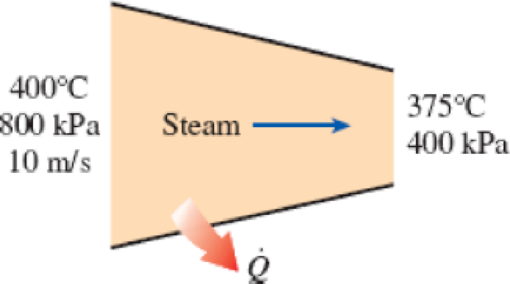
Steam enters a nozzle at 400°C and 800 kPa with a velocity of 10 m/s, and leaves at 375°C and 400 kPa while losing heat at a rate of 25 kW. For an inlet area of 800 cm2, determine the velocity and the volume flow rate of the steam at the nozzle exit.
FIGURE P5–33
The velocity and volume flow rate of the steam at the nozzle exit.
Answer to Problem 33P
The exit volume flow rate of the steam is
The exit velocity of the steam is
Explanation of Solution
Write the energy rate balance equation for one inlet and one outlet system.
Here, the rate of heat transfer is
Consider the steam flows at steady state through the nozzle. Hence, the rate of change in net energy of the system becomes zero.
Here, the heat loss from the nozzle is estimated as
There is no heat transfer at inlet i.e.
The Equations (I) reduced as follows to obtain the exit velocity.
At steady flow, the inlet and exit mass flow rates are equal.
Write the formula for inlet mass flow rate.
Here, the cross-sectional area is
Write the formula for exit volumetric flow rate.
At both the inlet and exit of the nozzle, the steam is at the state of superheated condition.
Refer Table A-6, “Superheated water”.
At inlet:
Obtain the following properties corresponding to the temperature of
At outlet:
Obtain the following properties corresponding to the temperature of
Write the formula of interpolation method of two variables.
Show the temperature and enthalpy values from the Table A-6 as in below table.
| S.No. | x | y |
| Temperature | Enthalpy | |
| 1 | 300 | 3067.1 |
| 2 | 375 | ? |
| 3 | 400 | 3273.9 |
Substitute
Thus, the enthalpy
Similarly, the exit specific volume
Conclusion:
Substitute
Substitute
Thus, the exit volume flow rate of the steam is
Substitute
Thus, the exit velocity of the steam is
Want to see more full solutions like this?
Chapter 5 Solutions
EBK THERMODYNAMICS: AN ENGINEERING APPR


- Q5:(? Design the duct system of the figure below by using the balanced pressure method. The velocity in the duct attached to the AHU must not exceed 5m/s. The pressure loss for each diffuser is equal to 10Pa. 100CFM 100CFM 100CFM ☑ ☑ 40m AHU -16m- 8m- -12m- 57m 250CFM 40m -14m- 26m 36m ☑ 250CFMarrow_forwardA mass of ideal gas in a closed piston-cylinder system expands from 427 °C and 16 bar following the process law, pv1.36 = Constant (p times v to the power of 1.36 equals to a constant). For the gas, initial : final pressure ratio is 4:1 and the initial gas volume is 0.14 m³. The specific heat of the gas at constant pressure, Cp = 0.987 kJ/kg-K and the specific gas constant, R = 0.267 kJ/kg.K. Determine the change in total internal energy in the gas during the expansion. Enter your numerical answer in the answer box below in KILO JOULES (not in Joules) but do not enter the units. (There is no expected number of decimal points or significant figures).arrow_forwardmy ID# 016948724. Please solve this problem step by steparrow_forward
- My ID# 016948724 please find the forces for Fx=0: fy=0: fz=0: please help me to solve this problem step by steparrow_forwardMy ID# 016948724 please solve the proble step by step find the forces fx=o: fy=0; fz=0; and find shear moment and the bending moment diagran please draw the diagram for the shear and bending momentarrow_forwardMy ID#016948724. Please help me to find the moment of inertia lx ly are a please show to solve step by stepsarrow_forward
- My ID# 016948724arrow_forwardPlease do not use any AI tools to solve this question. I need a fully manual, step-by-step solution with clear explanations, as if it were done by a human tutor. No AI-generated responses, please.arrow_forwardPlease do not use any AI tools to solve this question. I need a fully manual, step-by-step solution with clear explanations, as if it were done by a human tutor. No AI-generated responses, please.arrow_forward
 Refrigeration and Air Conditioning Technology (Mi...Mechanical EngineeringISBN:9781305578296Author:John Tomczyk, Eugene Silberstein, Bill Whitman, Bill JohnsonPublisher:Cengage Learning
 Principles of Heat Transfer (Activate Learning wi...Mechanical EngineeringISBN:9781305387102Author:Kreith, Frank; Manglik, Raj M.Publisher:Cengage Learning
 International Edition---engineering Mechanics: St...Mechanical EngineeringISBN:9781305501607Author:Andrew Pytel And Jaan KiusalaasPublisher:CENGAGE L