
Videos
A tank with an internal volume of 1 m3 contains air at 800 kPa and 25°C. A valve on the tank is opened, allowing air to escape, and the pressure inside quickly drops to 150 kPa, at which point the valve is closed. Assume there is negligible heat transfer from the tank to the air left in the tank.
- (a) Using the approximation he ≈ constant = he,avg = 0.5 (h1 + h2), calculate the mass withdrawn during the process.
- (b) Consider the same process but broken into two parts. That is, consider an intermediate state at P2 = 400 kPa, calculate the mass removed during the process from P1 = 800 kPa to P2 and then the mass removed during the process from P2 to P3 = 150 kPa, using the type of approximation used in part (a), and add the two to get the total mass removed.
- (c) Calculate the mass removed if the variation of he is accounted for.
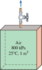
FIGURE P5–185
(a)
The mass withdrawn during the process.
Answer to Problem 185RP
The mass withdrawn during the process is
Explanation of Solution
Write the equation of mass balance.
Here, the inlet mass is
The change in mass of the system for the control volume is expressed as,
Here, the suffixes 1 and 2 indicates the initial and final states of the system.
Consider the tank as the control volume. Initially the tank is filled with air and the valve is in closed position, further no other mass is allowed to enter the tank. Hence, the inlet mass is neglected i.e.
Rewrite the Equation (I) as follows.
Write the formula for initial and final mass of air present in the tank.
Here, the mass of air is
Write the energy balance equation.
Here, the heat transfer is
When the valve is opened and air starts escape from the tank. Neglect the heat transfer and work done i.e.
The Equation (V) reduced as follows.
The enthalpy and internal energy in terms of temperature and specific heats are expressed as follows.
Rewrite the Equation (VI) as follows.
The temperature of the air while exiting the tank is considered as the average temperature of initial and final temperatures.
Refer Table A-1, “Molar mass, gas constant, and critical-point properties”.
The gas constant
Refer Table A-2b, “Ideal-gas specific heats of various common gases”.
The specific heat at constant pressure
Conclusion:
Substitute
Substitute
Substitute
Use Engineering Equation Solver (EES) or online calculator to solve the Equation (VIII) and obtain the value of
Substitute
Substitute
Thus, the mass withdrawn during the process is
(b)
The mass withdrawn during the pressure reduced from
Answer to Problem 185RP
The total mass withdrawn during the process 1-3 is
Explanation of Solution
Consider Process 1-2:
The pressure drop from
Substitute
Substitute
Substitute
Use Engineering Equation Solver (EES) or online calculator to solve the Equation (IX) and obtain the value of
Substitute
Substitute
Thus, the mass withdrawn during the process 1-2 is
Consider Process 2-3:
The pressure drop from
Here,
Substitute
Substitute
Substitute
Use Engineering Equation Solver (EES) or online calculator to solve the Equation (X) and obtain the value of
Substitute
Substitute
Thus, the mass withdrawn during the process 2-3 is
The total mass withdrawn during the process 1-3 is as follows.
Thus, the total mass withdrawn during the process 1-3 is
(c)
The mass withdrawn during the process if there is variation in
Answer to Problem 185RP
The mass withdrawn during the process is
Explanation of Solution
Write the general mass balance equation.
Here, the inlet mass flow rate is
Refer Equation (XI).
Write the mass balance equation for the given system.
Rewrite the Equation (XII) as follows.
Write the general energy rate balance equation.
Here, the rate of total energy in is
The system is at steady state. Hence, the rate of change in net energy of the system becomes zero.
Refer Equation (XIII).
Write the energy balance equation for the given system.
Here, the mass is
Substitute
The enthalpy and internal energy is expressed as follows.
Substitute
The mass of air in terms ideal gas is expressed as follows.
Rewrite the Equation (XVI) as follows.
Using
Substitute
Here,
Integrate the Equation (XVIII) at the initial-1 and final-2 states.
Refer Table A-2(a), “Ideal-gas specific heats of various common gases”.
The specific heat ratio
Conclusion:
Substitute
Substitute
Substitute
Thus, the mass withdrawn during the process is
Want to see more full solutions like this?
Chapter 5 Solutions
Thermodynamics: An Engineering Approach ( 9th International Edition ) ISBN:9781260092684
Additional Engineering Textbook Solutions
Fluid Mechanics: Fundamentals and Applications
Starting Out with C++ from Control Structures to Objects (9th Edition)
Management Information Systems: Managing The Digital Firm (16th Edition)
Automotive Technology: Principles, Diagnosis, And Service (6th Edition) (halderman Automotive Series)
Java: An Introduction to Problem Solving and Programming (8th Edition)
Starting Out with Programming Logic and Design (5th Edition) (What's New in Computer Science)


- PROBLEM 15.225 The bent rod shown rotates at the constant rate @₁ = 5 rad/s and collar C moves toward point B at a constant relative speed u = 39 in./s. Knowing that collar C is halfway between points B and D at the instant shown, determine its velocity and acceleration. Answers: v=-45 +36.6)-31.2 k in./s āc = -2911-270} in./s² 6 in 20.8 in. 14.4 in.arrow_forwardNeed help, please show all work, steps, units and please box out and round answers to 3 significant figures. Thank you!..arrow_forwardNeed help, please show all work, steps, units and please box out and round answers to 3 significant figures. Thank you!...arrow_forward
- FL y b C Z Determine the moment about O due to the force F shown, the magnitude of the force F = 76.0 lbs. Note: Pay attention to the axis. Values for dimensions on the figure are given in the following table. Note the figure may not be to scale. Variable Value a 1.90 ft b 2.80 ft с 2.60 ft d 2.30 ft Mo 144 ft-lb = -212 × 1 + xk) ☑+212arrow_forward20 in. PROBLEM 15.206 Rod AB is connected by ball-and-socket joints to collar A and to the 16-in.-diameter disk C. Knowing that disk C rotates counterclockwise at the constant rate ₁ =3 rad/s in the zx plane, determine the velocity of collar A for the position shown. 25 in. B 8 in. Answer: -30 in/s =arrow_forwardB Z 001 2.5 ft PROBLEM 15.236 The arm AB of length 16 ft is used to provide an elevated platform for construction workers. In the position shown, arm AB is being raised at the constant rate de/dt = 0.25 rad/s; simultaneously, the unit is being rotated about the Y axis at the constant rate ₁ =0.15 rad/s. Knowing that 20°, determine the velocity and acceleration of Point B. Answers: 1.371 +3.76)+1.88k ft/s a=1.22 -0.342)-0.410k ft/s² Xarrow_forward
- F1 3 5 4 P F2 F2 Ꮎ Ꮎ b P 3 4 5 F1 The electric pole is subject to the forces shown. Force F1 245 N and force F2 = 310 N with an angle = 20.2°. Determine the moment about point P of all forces. Take counterclockwise moments to be positive. = Values for dimensions on the figure are given in the following table. Note the figure may not be to scale. Variable Value a 2.50 m b 11.3 m C 13.0 m The moment about point P is 3,414 m. × N- If the moment about point P sums up to be zero. Determine the distance c while all other values remained the same. 1.26 m.arrow_forwardZ 0.2 m B PROBLEM 15.224 Rod AB is welded to the 0.3-m-radius plate, which rotates at the constant rate ₁ = 6 rad/s. Knowing that collar D moves toward end B of the rod at a constant speed u = 1.3 m, determine, for the position shown, (a) the velocity of D, (b) the acceleration of D. Answers: 1.2 +0.5-1.2k m/s a=-7.21-14.4k m/s² A 0.25 m 0.3 marrow_forwardI am trying to code in MATLAB the equations of motion for malankovich orbitlal elements. But, I am having a problem with the B matrix. Since f matrix is 7x1 and a_d matrix has to be 3x1, the B matrix has to be 7x3. I don't know how that is possible. Can you break down the B matrix for me and let me know what size it is?arrow_forward
- I am trying to code the solution to the problem in the image in MATLAB. I wanted to know what is the milankovich constraint equation that is talked about in part b.arrow_forwardmylabmastering.pearson.com Chapter 12 - Lecture Notes.pptx: (MAE 272-01) (SP25) DY... P Pearson MyLab and Mastering Scoresarrow_forwardAir modeled as an ideal gas enters an insulated compressor at a temperature of 300 K and 100 kPa, and leaves at 600 kPa. The mass flowrate of air entering the compressor is 50 kg/hr, and the power consumed by the compressor is 3 kW. (Rair = 0.287 kJ/kg-K, k = 1.4, cp = 1.0045 kJ/kg-K, cv = 0.718 kJ/kg-K) Determine the isentropic exit temperature (Te,s) of the air in [K]. Determine the actual exit temperature (Te) of the air in [K]. Determine the isentropic efficiency of the compressor. (Answer: ηc,s = 93.3%) Determine the rate of entropy generated through the compressor in [kW/K]. (Answer: Ṡgen = 0.000397 kW/K)arrow_forwardarrow_back_iosSEE MORE QUESTIONSarrow_forward_ios
 Elements Of ElectromagneticsMechanical EngineeringISBN:9780190698614Author:Sadiku, Matthew N. O.Publisher:Oxford University Press
 Mechanics of Materials (10th Edition)Mechanical EngineeringISBN:9780134319650Author:Russell C. HibbelerPublisher:PEARSON
 Thermodynamics: An Engineering ApproachMechanical EngineeringISBN:9781259822674Author:Yunus A. Cengel Dr., Michael A. BolesPublisher:McGraw-Hill Education
 Control Systems EngineeringMechanical EngineeringISBN:9781118170519Author:Norman S. NisePublisher:WILEY
 Mechanics of Materials (MindTap Course List)Mechanical EngineeringISBN:9781337093347Author:Barry J. Goodno, James M. GerePublisher:Cengage Learning
 Engineering Mechanics: StaticsMechanical EngineeringISBN:9781118807330Author:James L. Meriam, L. G. Kraige, J. N. BoltonPublisher:WILEY