
Vector Mechanics for Engineers: Statics, 11th Edition
11th Edition
ISBN: 9780077687304
Author: Ferdinand P. Beer, E. Russell Johnston Jr., David Mazurek
Publisher: McGraw-Hill Education
expand_more
expand_more
format_list_bulleted
Concept explainers
Videos
Textbook Question
Chapter 5.4, Problem 5.96P
Consider the composite body shown. Determine (a) the value of
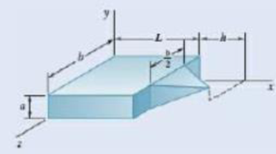
Fig. P5.96
Expert Solution & Answer
Want to see the full answer?
Check out a sample textbook solution
Students have asked these similar questions
Show work on how to obtain P2 and T2. If using any table, please refer to it. If applying interpolation method, please show the work.
cast-iron roller
FIGURE P11-3
Shaft Design for Problems 11-17
Chapter 11
BEARINGS AND LUBRICATION
677
gear
key
P
assume bearings act
as simple supports
11-18 Problem 7-18 determined the half-width of the contact patch for a 1.575-in-dia steel
cylinder, 9.843 in long, rolled against a flat aluminum plate with 900 lb of force to be
0.0064 in. If the cylinder rolls at 800 rpm, determine its lubrication condition with ISO
VG 1000 oil at 200°F. R₁ = 64 μin (cylinder); R₁ = 32 μin (plate).
11-19 The shaft shown in Figure P11-4 was designed in Problem 10-19. For the data in the
row(s) assigned from Table P11-1, and the corresponding diameter of shaft found in
Problem 10-19, design suitable bearings to support the load for at least 5E8 cycles at
1200 rpm. State all assumptions.
(a)
(b)
Using hydrodynamically lubricated bronze sleeve bearings with ON = 40,
1/ d=0.80, and a clearance ratio of 0.002 5.
Using deep-groove ball bearings for a 10% failure rate.
*11-20 Problem 7-20 determined the…
Calculate the shear force at the point D on the beam below. Take F=19 and remember that
this quantity is to be used to calculate both forces and lengths.
15F
A
с
Chapter 5 Solutions
Vector Mechanics for Engineers: Statics, 11th Edition
Ch. 5.1 - 5.1 through 5.9 Locate the centroid of the plane...Ch. 5.1 - 5.1 through 5.9 Locate the centroid of the plane...Ch. 5.1 - 5.1 through 5.9 Locate the centroid of the plane...Ch. 5.1 - Locate the centroid of the plane area shown.Ch. 5.1 - 5.1 through 5.9 Locate the centroid of the plane...Ch. 5.1 - Locate the centroid of the plane area shown.Ch. 5.1 - 5.1 through 5.9 Locate the centroid of the plane...Ch. 5.1 - Locate the centroid of the plane area shown.Ch. 5.1 - Locate the centroid of the plane area shown.Ch. 5.1 - Locate the centroid of the plane area shown.
Ch. 5.1 - 5.10 through 5.15 Locate the centroid of the plane...Ch. 5.1 - Locate the centroid of the plane area shown.Ch. 5.1 - 5.10 through 5.15 Locate the centroid of the plane...Ch. 5.1 - 5.10 through 5.15 Locate the centroid of the plane...Ch. 5.1 - 5.10 through 5.15 Locate the centroid of the plane...Ch. 5.1 - PROBLEM 5.16 Determine the y coordinate of the...Ch. 5.1 - Show that as r1 approaches r2, the location of the...Ch. 5.1 - Prob. 5.18PCh. 5.1 - For the semiannular area of Prob. 5.12, determine...Ch. 5.1 - Prob. 5.20PCh. 5.1 - Prob. 5.21PCh. 5.1 - The horizontal x-axis is drawn through the...Ch. 5.1 - PROBLEM 5.23 The first moment of the shaded area...Ch. 5.1 - Prob. 5.24PCh. 5.1 - Prob. 5.25PCh. 5.1 - Prob. 5.26PCh. 5.1 - A thin, homogeneous wire is bent to form the...Ch. 5.1 - The homogeneous wire ABC is bent into a...Ch. 5.1 - The frame for a sign is fabricated from thin, flat...Ch. 5.1 - The homogeneous wire ABCD is bent as shown and is...Ch. 5.1 - The homogeneous wire ABCD is bent as shown and is...Ch. 5.1 - Determine the distance h for which the centroid of...Ch. 5.1 - Knowing that the distance h has been selected to...Ch. 5.2 - 5.34 through 5.36 Determine by direct integration...Ch. 5.2 - 5.34 through 5.36 Determine by direct integration...Ch. 5.2 - 5.34 through 5.36 Determine by direct integration...Ch. 5.2 - 5.37 through 5.39 Determine by direct integration...Ch. 5.2 - 5.37 through 5.39 Determine by direct integration...Ch. 5.2 - 5.37 through 5.39 Determine by direct integration...Ch. 5.2 - 5.40 and 5.41 Determine by direct integration the...Ch. 5.2 - 5.40 and 5.41 Determine by direct integration the...Ch. 5.2 - Determine by direct integration the centroid of...Ch. 5.2 - 5.43 and 5.44 Determine by direct integration the...Ch. 5.2 - 5.43 and 5.44 Determine by direct integration the...Ch. 5.2 - 5.45 and 5.46 A homogeneous wire is bent into the...Ch. 5.2 - 5.45 and 5.46 A homogeneous wire is bent into the...Ch. 5.2 - A homogeneous wire is bent into the shape shown....Ch. 5.2 - 5.48 and 5.49 Determine by direct integration the...Ch. 5.2 - Prob. 5.49PCh. 5.2 - Determine the centroid of the area shown in terms...Ch. 5.2 - Determine the centroid of the area shown when a =...Ch. 5.2 - Prob. 5.52PCh. 5.2 - 5.53 Determine the volume and the surface area of...Ch. 5.2 - Determine the volume and the surface area of the...Ch. 5.2 - Prob. 5.55PCh. 5.2 - Prob. 5.56PCh. 5.2 - Verify that the expressions for the volumes of the...Ch. 5.2 - Knowing that two equal caps have been removed from...Ch. 5.2 - Three different drive belt profiles are to be...Ch. 5.2 - Determine the capacity, in liters, of the punch...Ch. 5.2 - Determine the volume and total surface area of the...Ch. 5.2 - Determine the volume and weight of the solid brass...Ch. 5.2 - Determine the total surface area of the solid...Ch. 5.2 - Prob. 5.64PCh. 5.2 - The shade for a wall-mounted light is formed from...Ch. 5.3 - 5.66 and 5.67 For the beam and loading shown,...Ch. 5.3 - 5.66 and 5.67 For the beam and loading shown,...Ch. 5.3 - Prob. 5.68PCh. 5.3 - 5.68 through 5.73 Determine the reactions at the...Ch. 5.3 - 5.68 through 5.73 Determine the reactions at the...Ch. 5.3 - 5.68 through 5.73 Determine the reactions at the...Ch. 5.3 - 5.68 through 5.73 Determine the reactions at the...Ch. 5.3 - 5.68 through 5.73 Determine the reactions at the...Ch. 5.3 - Determine (a) the distance a so that the vertical...Ch. 5.3 - Determine (a) the distance a so that the reaction...Ch. 5.3 - Prob. 5.76PCh. 5.3 - Prob. 5.77PCh. 5.3 - The beam AB supports two concentrated loads and...Ch. 5.3 - For the beam and loading of Prob. 5.78, determine...Ch. 5.3 - The cross section of a concrete dam is as shown....Ch. 5.3 - The cross section of a concrete dam is as shown....Ch. 5.3 - The dam for a lake is designed to withstand the...Ch. 5.3 - The base of a dam for a lake is designed to resist...Ch. 5.3 - 5.84 An automatic valve consists of a 9 × 9-in....Ch. 5.3 - Prob. 5.85PCh. 5.3 - The 3 4-m side AB of a tank is hinged at its...Ch. 5.3 - The 3 4-m side of an open tank is hinged at its...Ch. 5.3 - A 0.5 0.8-m gate AB is located at the bottom of a...Ch. 5.3 - A 0.5 0.8-m gate AB is located at the bottom of a...Ch. 5.3 - A 4 2-ft gate is hinged at A and is held in...Ch. 5.3 - Fig. P5.90 5.91 Solve Prob. 5.90 if the gate...Ch. 5.3 - A prismatically shaped gate placed at the end of a...Ch. 5.3 - A prismatically shaped gate placed at the end of a...Ch. 5.3 - A long trough is supported by a continuous hinge...Ch. 5.3 - The square gate AB is held in the position shown...Ch. 5.4 - Consider the composite body shown. Determine (a)...Ch. 5.4 - Prob. 5.97PCh. 5.4 - Prob. 5.98PCh. 5.4 - Prob. 5.99PCh. 5.4 - Prob. 5.100PCh. 5.4 - Prob. 5.101PCh. 5.4 - Prob. 5.102PCh. 5.4 - Prob. 5.103PCh. 5.4 - For the machine element shown, locate the y...Ch. 5.4 - For the machine element shown, locate the x...Ch. 5.4 - 5.106 and 5.107 Locate the center of gravity of...Ch. 5.4 - 5.106 and 5.107 Locate the center of gravity of...Ch. 5.4 - A corner reflector for tracking by radar has two...Ch. 5.4 - A wastebasket, designed to fit in the corner of a...Ch. 5.4 - An elbow for the duct of a ventilating system is...Ch. 5.4 - A window awning is fabricated from sheet metal...Ch. 5.4 - Prob. 5.112PCh. 5.4 - Prob. 5.113PCh. 5.4 - A thin steel wire with a uniform cross section is...Ch. 5.4 - The frame of a greenhouse is constructed from...Ch. 5.4 - Locate the center of gravity of the figure shown,...Ch. 5.4 - Prob. 5.117PCh. 5.4 - A scratch awl has a plastic handle and a steel...Ch. 5.4 - PROBLEM 5.117 A bronze bushing is mounted inside a...Ch. 5.4 - PROBLEM 5.120 A brass collar, of length 2.5 in.,...Ch. 5.4 - PROBLEM 5.121 The three legs of a small...Ch. 5.4 - Prob. 5.122PCh. 5.4 - Determine by direct integration the values of x...Ch. 5.4 - Prob. 5.124PCh. 5.4 - PROBLEM 5.125 Locate the centroid of the volume...Ch. 5.4 - Prob. 5.126PCh. 5.4 - Prob. 5.127PCh. 5.4 - PROBLEM 5.128 Locate the centroid of the volume...Ch. 5.4 - PROBLEM 5.129 Locate the centroid of the volume...Ch. 5.4 - Show that for a regular pyramid of height h and n...Ch. 5.4 - PROBLEM 5.131 Determine by direct integration the...Ch. 5.4 - PROBLEM 5.132 The sides and the base of a punch...Ch. 5.4 - Locate the centroid of the section shown, which...Ch. 5.4 - Locate the centroid of the section shown, which...Ch. 5.4 - Determine by direct integration the location of...Ch. 5.4 - Alter grading a lot, a builder places four stakes...Ch. 5 - 5.137 and 5.138 Locate the centroid of the plane...Ch. 5 - 5.137 and 5.138 Locate the centroid of the plane...Ch. 5 - Prob. 5.139RPCh. 5 - Determine by direct integration the centroid of...Ch. 5 - Determine by direct integration the centroid of...Ch. 5 - The escutcheon (a decorative plate placed on a...Ch. 5 - Determine the reactions at the supports for the...Ch. 5 - A beam is subjected to a linearly distributed...Ch. 5 - A tank is divided into two sections by a 1 1-m...Ch. 5 - Determine the y coordinate of the centroid of the...Ch. 5 - An 8-in.-diameter cylindrical duct and a 4 8-in....Ch. 5 - Three brass plates are brazed to a steel pipe to...
Knowledge Booster


Learn more about
Need a deep-dive on the concept behind this application? Look no further. Learn more about this topic, mechanical-engineering and related others by exploring similar questions and additional content below.Similar questions
- "II-1 The shaft shown in Figure P11-I was designed in Problem 10-1. For the data in the row(s) assigned from Table P11-1, and the corresponding diameter of shaft found in Problem 10-1, design suitable bearings to support the load for at least 7E7 cycles at 1500 rpm. State all assumptions. (a) Using hydrodynamically lubricated bronze sleeve bearings with Ox = 20, 1/d=1.25, and a clearance ratio of 0.001 5. assume bearings act as simple supports FIGURE P11-1 Shaft Design for Problem 11-1 11-2 The shaft shown in Figure P11-2 was designed in Problem 10-2. For the data in the row(s) assigned from Table P11-1, and the corresponding diameter of shaft found in Problem 10-2, design suitable bearings to support the load for at least 3E8 cycles at 2.500 rpm. State all assumptions. (a) Using hydrodynamically lubricated bronze sleeve bearings with ON=30, 1/d=1.0, and a clearance ratio of 0.002. FIGURE P11-2 Shaft Design for Problem 11-2 Table P11-1 Data for Problems assume bearings act as simple…arrow_forwardFor the frame below, calculate the shear force at point Q. Take P=13 and note that this value is used for both the loads and the lengths of the members of the frame. 1 A Q ✗ 19 KBP 2.5P- B R C 45 degrees ✗ 1 .2P- 4PhN -P→arrow_forwardCalculate the Bending Moment at point D in the frame below. Leave your answer in Nm (newton-metres) J J A 2m 2m <2m х D 不 1m X E 5m 325 Nm 4x 400N/marrow_forward
- In the beam below, calculate the shear force at point A. Take L=78 and remember that both the loads and the dimensions are expressed in terms of L. 143 1 DX A - Li 4 LhN 14LRN/m Х B 22 3 L.arrow_forwardCalculate the Shear Force at Point F on the beam below. Keep your answer in Newtons and make shear force positive to the right. A х 2m <2m E D 5m 1m Хт 325N1m 400N/m 8arrow_forwardThe normal force at C on the beam below is equal to: A ShN C X 15h N 8 ○ OkN 2.5kN 10kN ○ 12.5kN 1m Im 1m 1m;arrow_forward
- Calculate the y coordinate of the of the centroid of the shape below. Take A= 18.5 8 6A 4A X 6Aarrow_forwardIn MATLAB write out a program to integrate the equations of motion of a rigid body. The inertia matrix is given by I = [125 0 0; 0 100 0; 0 0 75] which is a diagonal, where diag operator provides a matrix with given elements placed on its diagonal. Consider three cases where the body rotates 1 rad/sec about each principal axis. Integrate the resulting motion and study the angular rates and the resulting attitude (use any attitude coordinates). For each principal axis case, assume first that a pure spin about the principal axis is performed, and then repeat the simulation where a small 0.1 rad/sec motion is present about another principal axis. Discuss the stability of each motion. The code should produce a total of 6 simulations results when it is ran.arrow_forwardQ. A strain gauge rosette that is attached to the surface of a stressed component C). If the strain gauge rosette is of the D° gives 3 readings (a = A, b = B, &c = type (indicating the angle between each of the gauges), construct a Mohr's Strain Circle overleaf. You should assume that gauge A is aligned along the x-axis. Using the Mohr's Strain Circle calculate the: [10 marks] 100 918 ucy evods gringiz ya mwo quoy al etsede 39 926919 (i) principal strains (1, 2)? (au) oniona [5 marks] (ii) principal angles (1, 2)? You should measure these anticlockwise from the y-axis. 20 [5 marks] (iii) maximum shear strain in the plane (ymax)? Ex = Ea Ey = εc [5 marks] (epol) (apob) é Ea = A = -210 2 B=E₁ = -50 E₁ = C = 340 D = 45° bril elled ✓A bedivordan nemigas olloho shot on no eonsoup Imeneo alubom shine sail-no viss ieqse sidetiva bnat sabied 2arrow_forward
- 1) Solve and show which is converage or diyverage a = 2+(0.1)" 3 16) a = n 1-2n 2) a = In n 1+2n 17) a = n 1-5n4 3) an = n* +8n³ 18) a =√4"n n² -2n+1 n! 20) a = 4) a₁ = 10 n-1 (Ina) 5) a=1+(-1)" 21) a= 6) a 7) an = * = (12+) (1-1) 2n (-1)+1 2n-1 3n+1 22) a= 3n-1 x" 23) a= .x>0 2n+1 2n 3"x6" 8) a = 24) a = n+1 π 9) a = sin 2 sin n 10) an = n + 2 x n! 25) a = tanh(n) n² 1 26) a = -sin- 2n-1 27) a = tan(n) n n 11) a = 2" 12) a = n 13) a = 8/ +=(1+2)" 14) a = 15) a = √10n In(n+1) 29) a = n 30) an-√n²-1 1 28) a = + √2" (In n)200 n 31) a=- = 1 dx nixarrow_forwardHW12 A multiple-disc clutch has five plates having four pairs of active friction surfaces. If the intensity of pressure is not to exceed 0.127 N/mm², find the power transmitted at 500 r.p.m. The outer and inner radii of friction surfaces are 125 mm and 75 mm respectively. Assume uniform wear and take the coefficient of friction = 0.3.arrow_forwardThe sketch below gives some details of the human heart at rest. What is the total power requirement (work/time) for an artificial heart pump if we use a safety factor of 5 to allow for inefficiencies, the need to operate the heart under stress, etc.? Assume blood has the properties of water. p pressure above atmosphere blood going to the lungs for a fresh charge of oxygen p = 2.9 kPa 25v pulmonary artery d = 25mm fresh oxygenated blood from the lungs p = 1.0 kPa vena cava d=30mm right auricle pulmonary vein, d = 28mm aorta, d=20mm spent blood returning from left auricle the body p = 0.66 kPa right left ventricle ventricle blood to feed the body, p 13 kPa normal blood flow = 90 ml/sarrow_forward
arrow_back_ios
SEE MORE QUESTIONS
arrow_forward_ios
Recommended textbooks for you
 Elements Of ElectromagneticsMechanical EngineeringISBN:9780190698614Author:Sadiku, Matthew N. O.Publisher:Oxford University Press
 Mechanics of Materials (10th Edition)Mechanical EngineeringISBN:9780134319650Author:Russell C. HibbelerPublisher:PEARSON
 Thermodynamics: An Engineering ApproachMechanical EngineeringISBN:9781259822674Author:Yunus A. Cengel Dr., Michael A. BolesPublisher:McGraw-Hill Education
 Control Systems EngineeringMechanical EngineeringISBN:9781118170519Author:Norman S. NisePublisher:WILEY
 Mechanics of Materials (MindTap Course List)Mechanical EngineeringISBN:9781337093347Author:Barry J. Goodno, James M. GerePublisher:Cengage Learning
 Engineering Mechanics: StaticsMechanical EngineeringISBN:9781118807330Author:James L. Meriam, L. G. Kraige, J. N. BoltonPublisher:WILEY
Elements Of Electromagnetics
Mechanical Engineering
ISBN:9780190698614
Author:Sadiku, Matthew N. O.
Publisher:Oxford University Press
Mechanics of Materials (10th Edition)
Mechanical Engineering
ISBN:9780134319650
Author:Russell C. Hibbeler
Publisher:PEARSON
Thermodynamics: An Engineering Approach
Mechanical Engineering
ISBN:9781259822674
Author:Yunus A. Cengel Dr., Michael A. Boles
Publisher:McGraw-Hill Education
Control Systems Engineering
Mechanical Engineering
ISBN:9781118170519
Author:Norman S. Nise
Publisher:WILEY
Mechanics of Materials (MindTap Course List)
Mechanical Engineering
ISBN:9781337093347
Author:Barry J. Goodno, James M. Gere
Publisher:Cengage Learning
Engineering Mechanics: Statics
Mechanical Engineering
ISBN:9781118807330
Author:James L. Meriam, L. G. Kraige, J. N. Bolton
Publisher:WILEY
Types Of loads - Engineering Mechanics | Abhishek Explained; Author: Prime Course;https://www.youtube.com/watch?v=4JVoL9wb5yM;License: Standard YouTube License, CC-BY