
Concept explainers
Videos
Locate the centroid of the section shown, which was cut f an elliptical cylinder by an oblique plane.
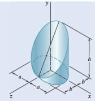
Fig. P5.134
The centroid of the section.
Answer to Problem 5.134P
The centroid of the section
Explanation of Solution
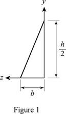
Refer Figure 1 and Figure 2.
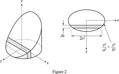
Consider an elemental section of the given section.
Write an expression to calculate the volume of the element.
Here,
From the symmetry, write an expression to calculate the distance of centroid of the section from x-axis.
Here,
From the symmetry, write an expression to calculate the distance of centroid of the section from x-axis.
Here,
Write an expression to calculate the distance of centroid of element from z-axis.
Here,
Write an expression to calculate width of the element.
Here,
Write an expression to calculate the height of the element.
Here,
Write an expression to calculate the volume of the section.
Write an expression to calculate the thickness of the section.
Differentiate the equation to calculate the thickness of the element.
Write an expression to find the distance of the centroid of the section from x axis.
Here,
Write an expression to find the distance of the centroid of the section from x axis.
Here,
Write an expression to find the distance of the centroid of the section from z axis.
Here,
Conclusion:
Substitute (V), (VI) and (IX) in equation (VII) to find
write an expression to calculate the distance of centroid of the element from x-axis.
Write an expression to calculate
Substitute equation (XIII) and (XIV) in equation (XI) to find
Write an expression to calculate
Substitute equation (XIII) and (XV) in equation (XII) to find
Thus, the centroid of the section
Want to see more full solutions like this?
Chapter 5 Solutions
Vector Mechanics for Engineers: Statics


- Problem 3. The assembly shown consists of a solid sphere of mass m and the uniform slender rod of the same mass, both of which are welded to the shaft. The assembly is rotating with angular velocity w at a particular moment. Find the angular momentum with respect to point O, in terms of the axes shown. Answer: Ñ。 = ½mc²wcosßsinßĵ + (}{mr²w + 2mb²w + ½ mc²wcos²ß) k 3 m r b 2 C لا marrow_forwardOnly question 2arrow_forwardOnly question 1arrow_forward
- Only question 3arrow_forwardI have Euler parameters that describe the orientation of N relative to Q, e = -0.7071*n3, e4 = 0.7071. I have Euler parameters that describe the orientation of U relative to N, e = -1/sqrt(3)*n1, e4 = sqrt(2/3). After using euler parameter rule of successive rotations, I get euler parameters that describe the orientation of U relative to Q, e = -0.4082*n1 - 0.4082*n2 - 0.5774*n3. I need euler parameters that describe the orientation of U relative to Q in vector basis of q instead of n. How do I get that?arrow_forwardDescribe at least 4 processes in engineering where control charts are (or should be) appliedarrow_forward
- Describe at least two (2) processes where control charts are (or should be) applied.arrow_forwardProblem 3: A cube-shaped spacecraft is in a circular Earth orbit. Let N (n,) be inertial and the spacecraft is denoted S (ŝ₁). The spacecraft is described such that ¯½º = J ŝ₁ŝ₁ + J ŝ₂§₂ + J §¸Ŝ3 Location of the spacecraft in the orbit is determined by the orbit-fixed unit vectors ê, that are oriented by the angle (Qt), where is a constant angular rate. 52 €3 3> 2t 55 Λ Из At the instant when Qt = 90°, the spacecraft S is oriented relative to the orbit such that 8₁ = 0° Space-three 1-2-3 angles 0₂ = 60° and ES = $₂ rad/s 0₁ = 135° (a) At this instant, determine the direction cosine matrix that describes the orientation of the spacecraft with respect to the inertial frame N.arrow_forwardThis problem illustrates that the factor of safety for a machine element depends on the particular point selected for analysis. Here you are to compute factors of safety, based upon the distortion-energy theory, for stress elements at A and B of the member shown in the figure. This bar is made of AISI 1006 cold-drawn steel and is loaded by the forces F = 1.100 kN, P = 8.00 kN, and T = 50.00 N-m. Given: Sy = 280 MPa. B -100 mm- 15-mm D. a) Determine the value of the axial stress at point B. b) Determine the value of the shear stress at point B. c) Determine the value of the Von Mises stress at point B. P Farrow_forward
- A piston-cylinder device initially contains 0.08 m^3 of nitrogen gas at 130 kPa and 170°C. The nitrogen is expanded to a pressure of 80 kPa via isentropic expansion. Determine the final temperature and the boundary work done by the system during this process.arrow_forwardA Carnot (ideal) heat pump is to be used to heat a house and maintain it at 22°C in winter. On a day when the average outdoor temperature remains at about 0°C, the house is estimated to lose heat at a rate of 65,000 kJ/h. If the heat pump consumes 6 kW of power while operating, determine: (a) how long the heat pump ran on that day (b) the total heating costs, assuming an average price of 11¢/kWh for electricity (c) the heating cost for the same day if an 85% efficient electric furnace is used instead of a heat pump.arrow_forwardFrom the information in the image, I needed to find the orientation of U relative to Q in vector basis q_hat. I transformed the euler angle/axis representation to euler parameters. Then I got its conjugate in order to get the euler parameter in N frame relative to Q. The problem gave the euler angle/axis representation in Q frame relative to N, so I needed to find the conjugate. Then I used the euler parameter rule of successive rotation to find the final euler parameters that describe the orientation of U relative to Q. However that orientation is in n_hat which is the intermediate frame. How do I get the final result in q_hat?arrow_forward
 Elements Of ElectromagneticsMechanical EngineeringISBN:9780190698614Author:Sadiku, Matthew N. O.Publisher:Oxford University Press
 Mechanics of Materials (10th Edition)Mechanical EngineeringISBN:9780134319650Author:Russell C. HibbelerPublisher:PEARSON
 Thermodynamics: An Engineering ApproachMechanical EngineeringISBN:9781259822674Author:Yunus A. Cengel Dr., Michael A. BolesPublisher:McGraw-Hill Education
 Control Systems EngineeringMechanical EngineeringISBN:9781118170519Author:Norman S. NisePublisher:WILEY
 Mechanics of Materials (MindTap Course List)Mechanical EngineeringISBN:9781337093347Author:Barry J. Goodno, James M. GerePublisher:Cengage Learning
 Engineering Mechanics: StaticsMechanical EngineeringISBN:9781118807330Author:James L. Meriam, L. G. Kraige, J. N. BoltonPublisher:WILEY