Concept explainers
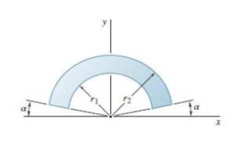
Show that as r1 approaches r2, the location of the centroid approaches that for an arc of circle of radius (r1 + r2)/2.

To show that as
Answer to Problem 5.17P
The location of the centroid for an arc of circle of radius
Explanation of Solution
Write the expression for the y-coordinate of the centroid of the sector with radius
Here
Write the expression for the area of the sector with radius
Write the expression for the y-coordinate of the centroid of the sector with radius
Here
Write the expression for the area of the sector with radius
Write the expression for
Substitute (I), (II), (III) and (IV) in the above equation to calculate
Write the expression for
Substitute (II) and (IV) in the above equation to calculate
Write the expression to calculate the y-coordinate of the centroid of the given area.
Substitute (V) and (VI) in the above equation to calculate
Write the expression for the y-coordinate of the centroid with an arc of radius
Rewrite the expression
Let
Substitute the above two expressions in (VIII) to rewrite.
Apply the limits
Rewrite r using
Conclusion:
Substitute (XII) in (VII) to calculate
Therefore, the above expression is same as that of the expression given in (VIII).
Thus, the location of the centroid for an arc of circle of radius
Want to see more full solutions like this?
Chapter 5 Solutions
Vector Mechanics for Engineers: Statics
- Problem 3.21P: Air at 100F(38C) db,65F(18C) wb, and sea-level pressure is humidified adiabatically with steam. The steam supplied contains 20 percent moisture(quality of 0.80) at 14.7psia(101.3kpa). The air is humidified to 60 percent relative humidity. Find the dry bulb temperature of the humidified air using (a)chart 1a or 1b and (b) the program PSYCH.arrow_forwardPUNTO 4. calculate their DoF using Gruebler's formula. PUNTO 5. Groundarrow_forwardPUNTO 2. PUNTO 3. calculate their DoF using Gruebler's formula. III IAarrow_forward
- calculate their DoF using Gruebler's formula. PUNTO 6. PUNTO 7. (Ctrl)arrow_forwardA pump delivering 230 lps of water at 30C has a 300-mm diameter suction pipe and a 254-mm diameter discharge pipe as shown in the figure. The suction pipe is 3.5 m long and the discharge pipe is 23 m long, both pipe's materials are cast iron. The water is delivered 16m above the intake water level. Considering head losses in fittings, valves, and major head loss. a) Find the total dynamic head which the pump must supply. b)It the pump mechanical efficiency is 68%, and the motor efficiency is 90%, determine the power rating of the motor in hp.given that: summation of K gate valve = 0.25check valve=390 degree elbow= 0.75foot valve= 0.78arrow_forwardA pump delivering 230 lps of water at 30C has a 300-mm diameter suction pipe and a 254-mm diameter discharge pipe as shown in the figure. The suction pipe is 3.5 m long and the discharge pipe is 23 m long, both pipe's materials are cast iron. The water is delivered 16m above the intake water level. Considering head losses in fittings, valves, and major head loss. a) Find the total dynamic head which the pump must supply. b)It the pump mechanical efficiency is 68%, and the motor efficiency is 90%, determine the power rating of the motor in hp.arrow_forward
- The tensile 0.2 percent offset yield strength of AISI 1137 cold-drawn steel bars up to 1 inch in diameter from 2 mills and 25 heats is reported as follows: Sy 93 95 101 f 97 99 107 109 111 19 25 38 17 12 10 5 4 103 105 4 2 where Sy is the class midpoint in kpsi and fis the number in each class. Presuming the distribution is normal, determine the yield strength exceeded by 99.0% of the population. The yield strength exceeded by 99.0% of the population is kpsi.arrow_forwardSolve this problem and show all of the workarrow_forwardI tried to go through this problem but I don't know what I'm doing wrong can you help me?arrow_forward
- Generate the kinematic diagram of the following mechanisms using the given symbols. Then, draw their graphs and calculate their degrees of freedom (DoF) using Gruebler's formula. PUNTO 2. PUNTO 3. !!!arrow_forwardCreate a schematic representation of the following mechanisms using the given symbols and draw their graphs. Then, calculate their degrees of freedom (DoF) using Gruebler's formula. PUNTO 6. PUNTO 7.arrow_forwardhow the kinematic diagram of the following mechanisms would be represented using the given symbols? PUNTO 0. PUNTO 1. °arrow_forward
 International Edition---engineering Mechanics: St...Mechanical EngineeringISBN:9781305501607Author:Andrew Pytel And Jaan KiusalaasPublisher:CENGAGE L
