
Engineering Mechanics: Statics & Dynamics (14th Edition)
14th Edition
ISBN: 9780133915426
Author: Russell C. Hibbeler
Publisher: PEARSON
expand_more
expand_more
format_list_bulleted
Concept explainers
Videos
Textbook Question
Chapter 5.4, Problem 16P
Determine the tension in the cable and the horizontal and vertical components of reaction of the pin A. The pulley at D is frictionless and the cylinder weighs 80 lb.
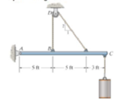
Prob. 5-16
Expert Solution & Answer
Want to see the full answer?
Check out a sample textbook solution
Students have asked these similar questions
A 22-lb block B rests as shown on a 28-lb bracket A. The coefficients of friction are μs=0.30μs=0.30 and μk=0.25μk=0.25 between block B and bracket A, and there is no friction in the pulley or between the bracket and the horizontal surface. solved in a previous part. max weight of block C if block B is not to slide on bracket A is 5.045 lbs. Please solve for the acceleration of each Block
Test 1 .DOCX * A
File Edit View
Tools Help
INDUSTRIAL ENGINEERING PROGRAMME
IMB 411-INDUSTRIAL LOGISTICS
TEST 1- SEPTEMBER 12, 2012
Instructions: Answer all questions. Time allowed is 1.5 hours. Identify your script with your
student number ONLY (Do not write your name).
1. Define the following terms
(i) Logistics management
(ii) Supply chain management
(iii) Vertical integration in a supply chain
(3 Marks)
(3 Marks)
(3 Marks)
2. (a) Using examples of your choice, briefly discuss the following levels of customer
service
(1) Pre-transaction elements
(ii) Transaction elements
(4 Marks)
(4 Marks)
(iii) Post-transaction elements
(4 Marks)
(b) "The challenge facing Dumelang Enterprise (Pty) Ltd is to establish the real
profitability of their customers and to develop service strategies that will improve the
profitability of all customers". As a logistics consultant, briefly discuss how you can
advise Dumelang's customer service management.
3. (a) List the three main forms of inventory in a…
It is decided to install several single-jet Pelton wheels to produce a total power of 18 MW. The
available head is 246 m. The wheel rotational speed is 650 rpm and the speed ratio (❤) = 0.46.
The diameter of the nozzle (jet) is limited to be 0.167 m with a Cv of 0.95. The efficiency of each
turbine is 87%. Determine: (1) The number of Pelton wheels to be used, and (2) The bucket
angle.
Chapter 5 Solutions
Engineering Mechanics: Statics & Dynamics (14th Edition)
Ch. 5.2 - Draw the free-body diagram for the following...Ch. 5.2 - Draw the free-body diagram for the following...Ch. 5.2 - Draw the free-body diagram for the following...Ch. 5.2 - Draw the free-body diagram for the following...Ch. 5.2 - Draw the free-body diagram for the following...Ch. 5.2 - Draw the free-body diagram for the following...Ch. 5.2 - Draw the free-body diagram for the following...Ch. 5.2 - Draw the free-body diagram for the following...Ch. 5.2 - Draw the free-body diagram for the following...Ch. 5.4 - Draw the free body diagram of each object. Prob....
Ch. 5.4 - Determine the horizontal and vertical components...Ch. 5.4 - Determine the horizontal and vertical components...Ch. 5.4 - The truss is supported by a pin at A and a roller...Ch. 5.4 - Prob. 4FPCh. 5.4 - The 25 kg bar has a center of mass at G. If it is...Ch. 5.4 - Prob. 6FPCh. 5.4 - Prob. 10PCh. 5.4 - Determine the reactions at the supports. Prob....Ch. 5.4 - Determine the horizontal and vertical components...Ch. 5.4 - Determine the reactions at the supports. Prob....Ch. 5.4 - Determine the reactions at the supports. Prob....Ch. 5.4 - Prob. 15PCh. 5.4 - Determine the tension in the cable and the...Ch. 5.4 - Prob. 17PCh. 5.4 - Determine the components of reaction at the...Ch. 5.4 - The man has a weight W and stands at the center of...Ch. 5.4 - A uniform glass rod having a length L is placed in...Ch. 5.4 - Prob. 21PCh. 5.4 - If the intensity of the distributed load acting on...Ch. 5.4 - Prob. 23PCh. 5.4 - Prob. 24PCh. 5.4 - Prob. 25PCh. 5.4 - The mobile crane is symmetrically supported by two...Ch. 5.4 - Prob. 27PCh. 5.4 - Prob. 28PCh. 5.4 - Determine the force P needed to pull the 50-kg...Ch. 5.4 - Prob. 30PCh. 5.4 - Prob. 31PCh. 5.4 - Determine the magnitude of force at the pin A and...Ch. 5.4 - The dimensions of a jib crane, which is...Ch. 5.4 - Prob. 34PCh. 5.4 - The smooth pipe rests against the opening at the...Ch. 5.4 - Prob. 36PCh. 5.4 - The cantilevered jib crane is used to support the...Ch. 5.4 - Prob. 38PCh. 5.4 - Prob. 39PCh. 5.4 - Determine the stiffness k of each spring so that...Ch. 5.4 - The bulk head AD Is subjected to both water and...Ch. 5.4 - The boom supports the two vertical loads. Neglect...Ch. 5.4 - Prob. 43PCh. 5.4 - The 10-kg uniform rod is pinned at end A. If It is...Ch. 5.4 - Prob. 45PCh. 5.4 - Prob. 46PCh. 5.4 - Prob. 47PCh. 5.4 - Prob. 48PCh. 5.4 - The rigid metal strip of negligible weight is used...Ch. 5.4 - Prob. 50PCh. 5.4 - Prob. 51PCh. 5.4 - Prob. 52PCh. 5.4 - Prob. 53PCh. 5.4 - Prob. 54PCh. 5.4 - The uniform rod has a length I and weight W. It is...Ch. 5.4 - Prob. 56PCh. 5.4 - Prob. 57PCh. 5.4 - Prob. 58PCh. 5.4 - The rod supports a weight of 200 lb and is pinned...Ch. 5.4 - Prob. 60PCh. 5.4 - Prob. 61PCh. 5.4 - The man attempts to pull the tour wheeler up the...Ch. 5.4 - Where is the best place to arrange most of the...Ch. 5.7 - Draw the free-body diagram of each object.Ch. 5.7 - In each case, write the moment equations about the...Ch. 5.7 - Prob. 7FPCh. 5.7 - Prob. 8FPCh. 5.7 - Prob. 9FPCh. 5.7 - Determine the support reactions at the smooth...Ch. 5.7 - Prob. 11FPCh. 5.7 - Determine the components of reaction that the...Ch. 5.7 - The uniform loads has a mass of 600 kg and is...Ch. 5.7 - Due to equal distribution of fuel in the wing...Ch. 5.7 - Prob. 5-63 5-64. Determine the components of...Ch. 5.7 - Prob. 65PCh. 5.7 - The smooth uniform rod AB is supported by a...Ch. 5.7 - The uniform concrete slab has a mass of 2400 kg....Ch. 5.7 - The 100-lb door has its center of gravity at G....Ch. 5.7 - Determine me tension in each cable and the...Ch. 5.7 - The stiff-leg derrick used on ships is supported...Ch. 5.7 - Determine the components of reaction at the...Ch. 5.7 - Determine the components of reaction at the...Ch. 5.7 - The bent rod is supported at A, B, and C by smooth...Ch. 5.7 - The bent rod is supported at A, B, and C by smooth...Ch. 5.7 - Prob. 75PCh. 5.7 - Prob. 76PCh. 5.7 - The member is supported by a square rod which fits...Ch. 5.7 - Prob. 78PCh. 5.7 - Prob. 79PCh. 5.7 - The bar AB is supported by two smooth collars. At...Ch. 5.7 - Prob. 81PCh. 5.7 - Prob. 82PCh. 5.7 - Prob. 83PCh. 5.7 - Both pulleys are fixed to the shaft and as the...Ch. 5.7 - Member AB is supported by a cable BC and at A by a...Ch. 5.7 - If the roller at 8 can sustain a maximum load of 3...Ch. 5.7 - Determine the reactions at the supports A and B...Ch. 5.7 - Prob. 3RPCh. 5.7 - Prob. 4RPCh. 5.7 - Determine the x, y, z components of reaction at...Ch. 5.7 - Prob. 6RPCh. 5.7 - Determine the x, y, z components of reaction at...Ch. 5.7 - Determine the x and z components of reaction at...
Knowledge Booster


Learn more about
Need a deep-dive on the concept behind this application? Look no further. Learn more about this topic, mechanical-engineering and related others by exploring similar questions and additional content below.Similar questions
- (I) [40 Points] Using centered finite difference approximations as done in class, solve the equation for O: d20 dx² + 0.010+ Q=0 subject to the boundary conditions shown in the stencil below. Do this for two values of Q: (a) Q = 0.3, and (b) Q= √(0.5 + 2x)e-sinx (cos(5x)+x-0.5√1.006-x| + e −43*|1+.001+x* | * sin (1.5 − x) + (cosx+0.001 + ex-1250+ sin (1-0.9x)|) * x - 4.68x4. For Case (a) (that is, Q = 0.3), use the stencil in Fig. 1. For Case (b), calculate with both the stencils in Fig. 1 and Fig 2. For all the three cases, show a table as well as a plot of O versus x. Discuss your results. Use MATLAB and hand in the MATLAB codes. 1 0=0 x=0 2 3 4 0=1 x=1 Fig 1 1 2 3 4 5 6 7 8 9 10 11 0=0 x=0 0=1 x=1 Fig 2arrow_forwardFig 2 (II) [60 Points] Using centered finite difference approximation as done in class, solve the equation: 020 020 + მx2 მy2 +0.0150+Q=0 subject to the boundary conditions shown in the stencils below. Do this for two values of Q: (a) Q = 0.3, and (b) Q = 10.5x² + 1.26 * 1.5 x 0.002 0.008. For Case (a) (that is, Q = 0.3) use Fig 3. For Case (b), use both Fig. 3 and Fig 4. For all the three cases, show a table as well as the contour plots of versus (x, y), and the (x, y) heat flux values at all the nodes on the boundaries x = 1 and y = 1. Discuss your results. Use MATLAB and hand in the MATLAB codes. (Note that the domain is (x, y)e[0,1] x [0,1].) 0=0 0=0 4 8 12 16 10 Ꮎ0 15 25 9 14 19 24 3 11 15 0=0 8-0 0=0 3 8 13 18 23 2 6 сл 5 0=0 10 14 6 12 17 22 1 6 11 16 21 13 e=0 Fig 3 Fig 4 Textbook: Numerical Methods for Engineers, Steven C. Chapra and Raymond P. Canale, McGraw-Hill, Eighth Edition (2021).arrow_forwardShip construction question. Sketch and describe the forward arrangements of a ship. Include componets of the structure and a explanation of each part/ term. Ive attached a general fore end arrangement. Simplfy construction and give a brief describion of the terms.arrow_forward
- Problem 1 Consider R has a functional relationship with variables in the form R = K xq xx using show that n ✓ - (OR 1.) = i=1 2 Их Ux2 Ихэ 2 (177)² = ² (1)² + b² (12)² + c² (1)² 2 UR R x2 x3arrow_forward4. Figure 3 shows a crank loaded by a force F = 1000 N and Mx = 40 Nm. a. Draw a free-body diagram of arm 2 showing the values of all forces, moments, and torques that act due to force F. Label the directions of the coordinate axes on this diagram. b. Draw a free-body diagram of arm 2 showing the values of all forces, moments, and torques that act due to moment Mr. Label the directions of the coordinate axes on this diagram. Draw a free body diagram of the wall plane showing all the forces, torques, and moments acting there. d. Locate a stress element on the top surface of the shaft at A and calculate all the stress components that act upon this element. e. Determine the principal stresses and maximum shear stresses at this point at A.arrow_forward3. Given a heat treated 6061 aluminum, solid, elliptical column with 200 mm length, 200 N concentric load, and a safety factor of 1.2, design a suitable column if its boundary conditions are fixed-free and the ratio of major to minor axis is 2.5:1. (Use AISC recommended values and round the ellipse dimensions so that both axes are whole millimeters in the correct 2.5:1 ratio.)arrow_forward
- 1. A simply supported shaft is shown in Figure 1 with w₁ = 25 N/cm and M = 20 N cm. Use singularity functions to determine the reactions at the supports. Assume El = 1000 kN cm². Wo M 0 10 20 30 40 50 60 70 80 90 100 110 cm Figure 1 - Problem 1arrow_forwardPlease AnswerSteam enters a nozzle at 400°C and 800 kPa with a velocity of 10 m/s and leaves at 375°C and 400 kPa while losing heat at a rate of 26.5 kW. For an inlet area of 800 cm2, determine the velocity and the volume flow rate of the steam at the nozzle exit. Use steam tables. The velocity of the steam at the nozzle exit is m/s. The volume flow rate of the steam at the nozzle exit is m3/s.arrow_forward2. A support hook was formed from a rectangular bar. Find the stresses at the inner and outer surfaces at sections just above and just below O-B. -210 mm 120 mm 160 mm 400 N B thickness 8 mm = Figure 2 - Problem 2arrow_forward
arrow_back_ios
SEE MORE QUESTIONS
arrow_forward_ios
Recommended textbooks for you
 International Edition---engineering Mechanics: St...Mechanical EngineeringISBN:9781305501607Author:Andrew Pytel And Jaan KiusalaasPublisher:CENGAGE L
International Edition---engineering Mechanics: St...
Mechanical Engineering
ISBN:9781305501607
Author:Andrew Pytel And Jaan Kiusalaas
Publisher:CENGAGE L
Force | Free Body Diagrams | Physics | Don't Memorise; Author: Don't Memorise;https://www.youtube.com/watch?v=4Bwwq1munB0;License: Standard YouTube License, CC-BY