
Videos
5.48 and *5.49 Determine by direct integration the centroid of the area shown.
Fig. P5.48
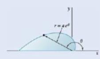
The centroid of shaded area in Fig. P5.48 by method of direct integration.
Answer to Problem 5.48P
Centroid is located at
Explanation of Solution
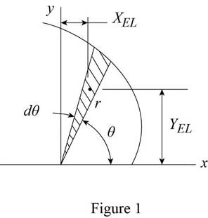
Refer the figure P5.48 and figure given below.
Write the equation for curve
Here,
In the figure given above, black dot denotes the center of mass of triangular shaped differential area element.
Write the expression for the x-coordinate of center of mass of triangular shaped differential area element.
Here,
Rewrite the above relation by substituting
Write the expression for the y-coordinate of center of mass of triangular shaped differential area element.
Here,
Rewrite the above relation by substituting
Write the expression to calculate the triangular differential area element.
Here,
Rewrite the above relation by substituting
Write the expression to calculate the total area of shaded region in P5.48.
Here,
Rewrite the above equation by substituting
Calculate
Apply the integration by parts method to solve the above integral. The required formula is given below.
Here,
Substitute
Rewrite the above equation in terms of
Calculate
Rewrite equation (I) by substituting the above result.
\
Calculate
Apply the integration by parts method to solve the above integral. The required formula is given below.
Here,
Substitute
Rewrite the above equation in terms of
Calculate
Rewrite equation (I) by substituting the above result.
Write the expression for first moment of whole area about y-axis.
Here,
Rewrite the above relation by substituting
Rewrite the above relation in terms of
Write the expression for first moment of whole area about x-axis.
Here,
Rewrite the above relation in terms of
Therefore, the centroid is located at
Want to see more full solutions like this?
Chapter 5 Solutions
VECTOR MECHANICS FOR ENGINEERS W/CON >B


- Problem 3.30 A piston-cylinder device contains 0.85 kg of refrigerant- 134a at -10°C. The piston that is free to move has a mass of 12 kg and a diameter of 25 cm. The local atmospheric pressure is 100 kPa. Now, heat is transferred to refrigerant-134a until the temperature is 15°C. Determine (a) the final pressure, (b) the change in the volume of the refrigerant, and (c) the change in the enthalpy of the refrigerant-134a. please show Al work step by steparrow_forwardPart 1 The storage tank contains lubricating oil of specific gravity 0.86 In one inclined side of the tank, there is a 0.48 m diameter circular inspection door, mounted on a horizontal shaft along the centre line of the gate. The oil level in the tank rests 8.8 m above the mounted shaft. (Please refer table 01 for relevant SG, D and h values). Describe the hydrostatic force and centre of pressure with the aid of a free body diagram of the inspection door. Calculate the magnitude of the hydrostatic force and locate the centre of pressure. 45° Estimate the moment that would have to be applied to the shaft to open the gate. Stop B If the oil level raised by 2 m from the current level, calculate the new moment required to open the gate. Figure 01arrow_forwardFrom thermodynamics please fill in the table show all work step by steparrow_forward
- The 150-lb skater passes point A with a speed of 6 ft/s. (Figure 1) Determine his speed when he reaches point B. Neglect friction. Determine the normal force exerted on him by the track at this point. 25 ft B = 4x A 20 ft xarrow_forwardA virtual experiment is designed to determine the effect of friction on the timing and speed of packages being delivered to a conveyor belt and the normal force applied to the tube. A package is held and then let go at the edge of a circular shaped tube of radius R = 5m. The particle at the bottom will transfer to the conveyor belt, as shown below. Run the simulations for μ = 0, 0.1, 0.2, 0.3, 0.4, 0.5, 0.6 and determine the time and speed at which the package is delivered to the conveyor belt. In addition, determine the maximum normal force and its location along the path as measured by angle 0. Submit in hardcopy form: (0) Free Body Diagram, equations underneath, derivations (a) Your MATLAB mfile (b) A table listing the values in 5 columns: μ, T (time of transfer), V (speed of transfer), 0 (angle of max N), Nmax (max N) (c) Based on your results, explain in one sentence what you think will happen to the package if the friction is increased even further, e.g. μ = 0.8. NOTE: The ODE is…arrow_forwardPatm = 1 bar Piston m = 50 kg 5 g of Air T₁ = 600 K P₁ = 3 bar Stops A 9.75 x 10⁻³ m² FIGURE P3.88arrow_forward
- Assume a Space Launch System (Figure 1(a)) that is approximated as a cantilever undamped single degree of freedom (SDOF) system with a mass at its free end (Figure 1(b)). The cantilever is assumed to be massless. Assume a wind load that is approximated with a concentrated harmonic forcing function p(t) = posin(ωt) acting on the mass. The known properties of the SDOF and the applied forcing function are given below. • Mass of SDOF: m =120 kip/g • Acceleration of gravity: g = 386 in/sec2 • Bending sectional stiffness of SDOF: EI = 1015 lbf×in2 • Height of SDOF: h = 2000 inches • Amplitude of forcing function: po = 6 kip • Forcing frequency: f = 8 Harrow_forwardAssume a Space Launch System (Figure 1(a)) that is approximated as a cantilever undamped single degree of freedom (SDOF) system with a mass at its free end (Figure 1(b)). The cantilever is assumed to be massless. Assume a wind load that is approximated with a concentrated harmonic forcing function p(t) = posin(ωt) acting on the mass. The known properties of the SDOF and the applied forcing function are given below. • Mass of SDOF: m =120 kip/g • Acceleration of gravity: g = 386 in/sec2 • Bending sectional stiffness of SDOF: EI = 1015 lbf×in2 • Height of SDOF: h = 2000 inches • Amplitude of forcing function: po = 6 kip • Forcing frequency: f = 8 Hz Figure 1: Single-degree-of-freedom system in Problem 1. Please compute the following considering the steady-state response of the SDOF system. Do not consider the transient response unless it is explicitly stated in the question. (a) The natural circular frequency and the natural period of the SDOF. (10 points) (b) The maximum displacement of…arrow_forwardAssume a Space Launch System (Figure 1(a)) that is approximated as a cantilever undamped single degree of freedom (SDOF) system with a mass at its free end (Figure 1(b)). The cantilever is assumed to be massless. Assume a wind load that is approximated with a concentrated harmonic forcing function p(t) = posin(ωt) acting on the mass. The known properties of the SDOF and the applied forcing function are given below. • Mass of SDOF: m =120 kip/g • Acceleration of gravity: g = 386 in/sec2 • Bending sectional stiffness of SDOF: EI = 1015 lbf×in2 • Height of SDOF: h = 2000 inches • Amplitude of forcing function: po = 6 kip • Forcing frequency: f = 8 Hz Figure 1: Single-degree-of-freedom system in Problem 1. Please compute the following considering the steady-state response of the SDOF system. Do not consider the transient response unless it is explicitly stated in the question. (a) The natural circular frequency and the natural period of the SDOF. (10 points) (b) The maximum displacement of…arrow_forward
- Please solve 13 * √(2675.16)² + (63.72 + 2255,03)² = 175x106 can you explain the process for getting d seperate thank youarrow_forwardIf the 300-kg drum has a center of mass at point G, determine the horizontal and vertical components of force acting at pin A and the reactions on the smooth pads C and D. The grip at B on member DAB resists both horizontal and vertical components of force at the rim of the drum. P 60 mm; 60 mm: 600 mm A E 30° B C 390 mm 100 mm D Garrow_forwardThe design of the gear-and-shaft system shown requires that steel shafts of the same diameter be used for both AB and CD. It is further required that the angle D through which end D of shaft CD rotates not exceed 1.5°. Knowing that G = 77.2 GPa, determine the required diameter of the shafts. 40 mm 400 mm 100 mm 600 mm T-1000 N-m Darrow_forward
 Elements Of ElectromagneticsMechanical EngineeringISBN:9780190698614Author:Sadiku, Matthew N. O.Publisher:Oxford University Press
 Mechanics of Materials (10th Edition)Mechanical EngineeringISBN:9780134319650Author:Russell C. HibbelerPublisher:PEARSON
 Thermodynamics: An Engineering ApproachMechanical EngineeringISBN:9781259822674Author:Yunus A. Cengel Dr., Michael A. BolesPublisher:McGraw-Hill Education
 Control Systems EngineeringMechanical EngineeringISBN:9781118170519Author:Norman S. NisePublisher:WILEY
 Mechanics of Materials (MindTap Course List)Mechanical EngineeringISBN:9781337093347Author:Barry J. Goodno, James M. GerePublisher:Cengage Learning
 Engineering Mechanics: StaticsMechanical EngineeringISBN:9781118807330Author:James L. Meriam, L. G. Kraige, J. N. BoltonPublisher:WILEY