
Videos
5.43 and 5.44
Determine by direct integration the centroid of the area shown. Express your answer in terms of a and b.
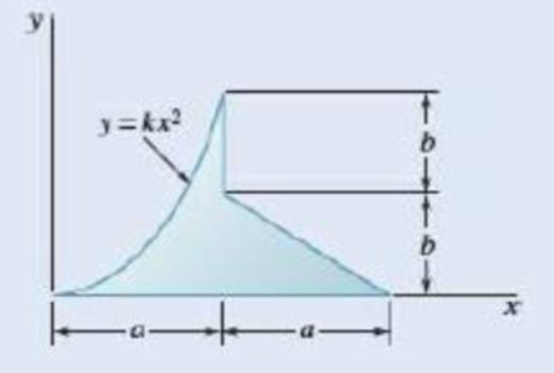
Fig. P5.44
The centroid of shaded area in Fig. P5.44 by method of direct integration.
Answer to Problem 5.44P
Centroid is located at
Explanation of Solution
Refer the figure P5.44 and figure given below.

Write the equation for curve
Here,
Consider the point
Here,
Rewrite equation (I) by substituting
Rewrite the above equation in terms of
Rewrite equation (I) by substituting the above relation for
Divide the shaded region in P5.44 into two parts for the purpose of integration. Region
Consider the region
Consider a rectangular differential area element in the region. Write the expression for the x-coordinate of center of mass of differential area element.
Here,
Write the expression for the y-coordinate of center of mass of differential area element in region
Here,
Rewrite the above relation by substituting
Write the expression to calculate the differential area element in
Here,
Rewrite the above relation by substituting
Consider the region
Write the expression for the x-coordinate of center of mass of differential area element in region
Here,
Write the expression for the y-coordinate of center of mass of differential area element in region
Here,
Calculate the slope of
Here,
Write the equation of
Rewrite the above equation by substituting
Rewrite equation (IV) by substituting
Write the expression for
Rewrite the above relation by substituting
Write the equation to calculate the total area of shaded region in P5.44.
Here,
Rewrite the above equation by substituting equation (III) and (VI).
Write the expression for
Rewrite the above equation by substituting equation (III) and (VI).
Write the expression for
Rewrite the above equation by substituting equations (II), (III), (V) and (VI).
Write the expression for first moment of whole area about y-axis.
Here,
Rewrite the above relation by substituting
Rewrite the above relation in terms of
Write the expression for first moment of whole area about x-axis.
Here,
Rewrite the above relation in terms of
Therefore, the centroid is located at
Want to see more full solutions like this?
Chapter 5 Solutions
VECTOR MECH...,STAT.+DYNA.(LL)-W/ACCESS


- Problem 1. The flywheel A has an angular velocity o 5 rad/s. Link AB is connected via ball and socket joints to the flywheel at A and a slider at B. Find the angular velocity of link AB and the velocity of slider B at this instant. (Partial Answer: @ABN = -2î + 2.25; red Z -1.2 ft C -7 Y -1.5 ft- B 2.0 ftarrow_forwardNeed help pleasearrow_forwardPROBLEM 15.225 The bent rod shown rotates at the constant rate @₁ = 5 rad/s and collar C moves toward point B at a constant relative speed u = 39 in./s. Knowing that collar C is halfway between points B and D at the instant shown, determine its velocity and acceleration. Answers: v=-45 +36.6)-31.2 k in./s āc = -2911-270} in./s² 6 in 20.8 in. 14.4 in.arrow_forward
- Need help, please show all work, steps, units and please box out and round answers to 3 significant figures. Thank you!..arrow_forwardNeed help, please show all work, steps, units and please box out and round answers to 3 significant figures. Thank you!...arrow_forwardFL y b C Z Determine the moment about O due to the force F shown, the magnitude of the force F = 76.0 lbs. Note: Pay attention to the axis. Values for dimensions on the figure are given in the following table. Note the figure may not be to scale. Variable Value a 1.90 ft b 2.80 ft с 2.60 ft d 2.30 ft Mo 144 ft-lb = -212 × 1 + xk) ☑+212arrow_forward
- 20 in. PROBLEM 15.206 Rod AB is connected by ball-and-socket joints to collar A and to the 16-in.-diameter disk C. Knowing that disk C rotates counterclockwise at the constant rate ₁ =3 rad/s in the zx plane, determine the velocity of collar A for the position shown. 25 in. B 8 in. Answer: -30 in/s =arrow_forwardB Z 001 2.5 ft PROBLEM 15.236 The arm AB of length 16 ft is used to provide an elevated platform for construction workers. In the position shown, arm AB is being raised at the constant rate de/dt = 0.25 rad/s; simultaneously, the unit is being rotated about the Y axis at the constant rate ₁ =0.15 rad/s. Knowing that 20°, determine the velocity and acceleration of Point B. Answers: 1.371 +3.76)+1.88k ft/s a=1.22 -0.342)-0.410k ft/s² Xarrow_forwardF1 3 5 4 P F2 F2 Ꮎ Ꮎ b P 3 4 5 F1 The electric pole is subject to the forces shown. Force F1 245 N and force F2 = 310 N with an angle = 20.2°. Determine the moment about point P of all forces. Take counterclockwise moments to be positive. = Values for dimensions on the figure are given in the following table. Note the figure may not be to scale. Variable Value a 2.50 m b 11.3 m C 13.0 m The moment about point P is 3,414 m. × N- If the moment about point P sums up to be zero. Determine the distance c while all other values remained the same. 1.26 m.arrow_forward
- Z 0.2 m B PROBLEM 15.224 Rod AB is welded to the 0.3-m-radius plate, which rotates at the constant rate ₁ = 6 rad/s. Knowing that collar D moves toward end B of the rod at a constant speed u = 1.3 m, determine, for the position shown, (a) the velocity of D, (b) the acceleration of D. Answers: 1.2 +0.5-1.2k m/s a=-7.21-14.4k m/s² A 0.25 m 0.3 marrow_forwardI am trying to code in MATLAB the equations of motion for malankovich orbitlal elements. But, I am having a problem with the B matrix. Since f matrix is 7x1 and a_d matrix has to be 3x1, the B matrix has to be 7x3. I don't know how that is possible. Can you break down the B matrix for me and let me know what size it is?arrow_forwardI am trying to code the solution to the problem in the image in MATLAB. I wanted to know what is the milankovich constraint equation that is talked about in part b.arrow_forward
 Elements Of ElectromagneticsMechanical EngineeringISBN:9780190698614Author:Sadiku, Matthew N. O.Publisher:Oxford University Press
 Mechanics of Materials (10th Edition)Mechanical EngineeringISBN:9780134319650Author:Russell C. HibbelerPublisher:PEARSON
 Thermodynamics: An Engineering ApproachMechanical EngineeringISBN:9781259822674Author:Yunus A. Cengel Dr., Michael A. BolesPublisher:McGraw-Hill Education
 Control Systems EngineeringMechanical EngineeringISBN:9781118170519Author:Norman S. NisePublisher:WILEY
 Mechanics of Materials (MindTap Course List)Mechanical EngineeringISBN:9781337093347Author:Barry J. Goodno, James M. GerePublisher:Cengage Learning
 Engineering Mechanics: StaticsMechanical EngineeringISBN:9781118807330Author:James L. Meriam, L. G. Kraige, J. N. BoltonPublisher:WILEY