
EBK MECHANICS OF MATERIALS
7th Edition
ISBN: 8220102804487
Author: BEER
Publisher: YUZU
expand_more
expand_more
format_list_bulleted
Concept explainers
Videos
Textbook Question
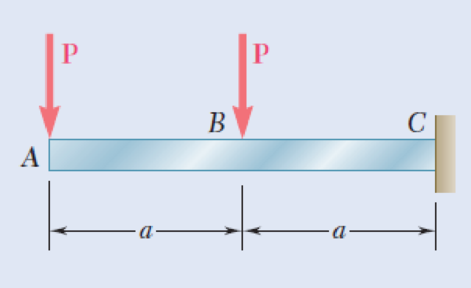
Chapter 5.1, Problem 5P
5.1 through 5.6 For the beam and loading shown, (a) draw the shear and bending-moment diagrams, (b) determine the equations of the shear and bending-moment curves.
Fig. P5.5
Expert Solution & Answer
Want to see the full answer?
Check out a sample textbook solution
Students have asked these similar questions
An elastic bar of length L = 1m and cross section A = 1cm2 spins with
angular velocity ω about an axis, as shown in the figure below. The
radial acceleration at a generic point x along the bar is a(x) = ω2x,
where ω= 100rad/s is the angular velocity. The bar is pinned on the
rotation axis at x = 0. A mass M = 1kg is attached to the right end of
the bar. Due to the radial acceleration, the bar stretches along x with
displacement function u(x). The displacement u(x) solves the BVP
(strong form) sketched below:
d
dx (σ(x)) + ρa(x) = 0 PDE
σ(x) = E du
dx Hooke’s law
(1)
u(0) =?? essential BC
σ(L) =?? natural BC
where σ(x) is the axial stress in the rod, ρ= 2700kg /m3 is the mass
density, and E = 70GPa is the Young’s modulus
1. Define appropriate BCs for the strong BVP
2. Find the solution of the strong BVP analytically
3. Derive the weak form of the BVP.
Gruebler's formula for the following mechanism?
w/I
- |
العنوان
I need a detailed drawing with explanation
SOLL
эт
4
حكا
The guide vane angle of a reaction turbine (Francis type
make 20° with the tangent. The moving blade angle at entry is
120°. The external diameter of runner is 450 mm and the internal
diameter is 300 mm. Runner width at entry is 62.5mm and at exit
100mm. Calculate the blade angle at exit for radial discharge.
96252
-20125
750 ×2.01
Chapter 5 Solutions
EBK MECHANICS OF MATERIALS
Ch. 5.1 - 5.1 through 5.6 For the beam and loading shown,...Ch. 5.1 - 5.1 through 5.6 For the beam and loading shown,...Ch. 5.1 - 5.1 through 5.6 For the beam and loading shown,...Ch. 5.1 - 5.1 through 5.6 For the beam and loading shown,...Ch. 5.1 - 5.1 through 5.6 For the beam and loading shown,...Ch. 5.1 - 5.1 through 5.6 For the beam and loading shown,...Ch. 5.1 - 5.7 and 5.8 Draw the shear and bending-moment...Ch. 5.1 - 5.7 and 5.8 Draw the shear and bending-moment...Ch. 5.1 - 5.9 and 5.10 Draw the shear and bending-moment...Ch. 5.1 - 5.9 and 5.10 Draw the shear and bending-moment...
Ch. 5.1 - 5.11 and 5.12 Draw the shear and bending-moment...Ch. 5.1 - 5.11 and 5.12 Draw the shear and bending-moment...Ch. 5.1 - 5.13 and 5.14 Assuming that the reaction of the...Ch. 5.1 - 5.13 and 5.14 Assuming that the reaction of the...Ch. 5.1 - 5.15 and 5.16 For the beam and loading shown,...Ch. 5.1 - 5.15 and 5.16 For the beam and loading shown,...Ch. 5.1 - For the beam and loading shown, determine the...Ch. 5.1 - For the beam and loading shown, determine the...Ch. 5.1 - 5.19 and 5.20 For the beam and loading shown,...Ch. 5.1 - 5.19 and 5.20 For the beam and loading shown,...Ch. 5.1 - Draw the shear and bending-moment diagrams for the...Ch. 5.1 - 5.22 and 5.23 Draw the shear and bending-moment...Ch. 5.1 - 5.22 and 5.23 Draw the shear and bending-moment...Ch. 5.1 - 5.24 and 5.25 Draw the shear and bending-moment...Ch. 5.1 - 5.24 and 5.25 Draw the shear and bending-moment...Ch. 5.1 - Knowing that W = 12 kN, draw the shear and...Ch. 5.1 - Determine (a) the magnitude of the counterweight W...Ch. 5.1 - Determine (a) the distance a for which the...Ch. 5.1 - Knowing that P = Q = 480 N, determine (a) the...Ch. 5.1 - Solve Prob. 5.29, assuming that P = 480 N and Q =...Ch. 5.1 - Determine (a) the distance a for which the...Ch. 5.1 - A solid steel rod of diameter d is supported as...Ch. 5.1 - A solid steel bar has a square cross section of...Ch. 5.2 - Using the method of Sec. 5.2, solve Prob. 5.1a....Ch. 5.2 - Using the method of Sec. 5.2, solve Prob. 5.2a....Ch. 5.2 - Prob. 36PCh. 5.2 - Prob. 37PCh. 5.2 - Using the method of Sec. 5.2, solve Prob. 5.5a....Ch. 5.2 - Using the method of Sec. 5.2, solve Prob. 5.6a....Ch. 5.2 - Using the method of Sec. 5.2, solve Prob. 5.7. 5.7...Ch. 5.2 - Using the method of Sec. 5.2, solve Prob. 5.8. 5.7...Ch. 5.2 - Prob. 42PCh. 5.2 - Using the method of Sec. 5.2, solve Prob. 5.10....Ch. 5.2 - 5.44 and 5.45 Draw the shear and bending-moment...Ch. 5.2 - 5.44 and 5.45 Draw the shear and bending-moment...Ch. 5.2 - Prob. 46PCh. 5.2 - Prob. 47PCh. 5.2 - Prob. 48PCh. 5.2 - Using the method of Sec. 5.2, solve Prob. 5.20....Ch. 5.2 - 5.50 and 5.51 Determine (a) the equations of the...Ch. 5.2 - 5.50 and 5.51 Determine (a) the equations of the...Ch. 5.2 - 5.52 and 5.53 Determine (a) the equations of the...Ch. 5.2 - 5.52 and 5.53 Determine (a) the equations of the...Ch. 5.2 - 5.54 and 5.55 Draw the shear and bending-moment...Ch. 5.2 - 5.54 and 5.55 Draw the shear and bending-moment...Ch. 5.2 - 5.56 and 5.57 Draw the shear and bending-moment...Ch. 5.2 - 5.56 and 5.57 Draw the shear and bending-moment...Ch. 5.2 - 5.58 and 5.59 Draw the shear and bending-moment...Ch. 5.2 - 5.58 and 5.59 Draw the shear and bending-moment...Ch. 5.2 - Knowing that beam AB is in equilibrium under the...Ch. 5.2 - Knowing that beam AB is in equilibrium under the...Ch. 5.2 - The beam AB supports two concentrated loads P and...Ch. 5.2 - The beam AB supports a uniformly distributed load...Ch. 5.2 - Beam AB supports a uniformly distributed load of 2...Ch. 5.3 - 5.65 and 5.66 For the beam and loading shown,...Ch. 5.3 - 5.65 and 5.66 For the beam and loading shown,...Ch. 5.3 - 5.67 and 5.68 For the beam and loading shown,...Ch. 5.3 - 5.67 and 5.68 For the beam and loading shown,...Ch. 5.3 - 5.69 and 5.70 For the beam and loading shown,...Ch. 5.3 - 5.69 and 5.70 For the beam and loading shown,...Ch. 5.3 - 5.71 and 5.72 Knowing that the allowable normal...Ch. 5.3 - 5.71 and 5.72 Knowing that the allowable normal...Ch. 5.3 - 5.73 and 5.74 Knowing that the allowable normal...Ch. 5.3 - 5.73 and 5.74 Knowing that the allowable normal...Ch. 5.3 - 5.75 and 5.76 Knowing that the allowable normal...Ch. 5.3 - 5.75 and 5.76 Knowing that the allowable normal...Ch. 5.3 - 5.77 and 5.78 Knowing that the allowable normal...Ch. 5.3 - 5.77 and 5.78 Knowing that the allowable normal...Ch. 5.3 - A steel pipe of 100-mm diameter is to support the...Ch. 5.3 - Two metric rolled-steel channels are to be welded...Ch. 5.3 - Two rolled-steel channels are to be welded back to...Ch. 5.3 - Two L4 3 rolled-steel angles are bolted together...Ch. 5.3 - Assuming the upward reaction of the ground to be...Ch. 5.3 - Assuming the upward reaction of the ground to be...Ch. 5.3 - Determine the largest permissible distributed load...Ch. 5.3 - Solve Prob. 5.85, assuming that the cross section...Ch. 5.3 - Determine the largest permissible value of P for...Ch. 5.3 - Solve Prob. 5.87, assuming that the T-shaped beam...Ch. 5.3 - Beams AB, BC, and CD have the cross section shown...Ch. 5.3 - Beams AB, BC, and CD have the cross section shown...Ch. 5.3 - Each of the three rolled-steel beams shown...Ch. 5.3 - A 54-kip load is to be supported at the center of...Ch. 5.3 - A uniformly distributed load of 66 kN/m is to be...Ch. 5.3 - A roof structure consists of plywood and roofing...Ch. 5.3 - Solve Prob. 5.94, assuming that the 6-kN...Ch. 5.3 - Prob. 96PCh. 5.3 - Assuming that the front and rear axle loads remain...Ch. 5.4 - 5.98 through 5.100 (a) Using singularity...Ch. 5.4 - 5.98 through 5.100 (a) Using singularity...Ch. 5.4 - 5.98 through 5.100 (a) Using singularity...Ch. 5.4 - 5.101 through 5.103 (a) Using singularity...Ch. 5.4 - Prob. 102PCh. 5.4 - Prob. 103PCh. 5.4 - Prob. 104PCh. 5.4 - Prob. 105PCh. 5.4 - Prob. 106PCh. 5.4 - Prob. 107PCh. 5.4 - Prob. 108PCh. 5.4 - Prob. 109PCh. 5.4 - Prob. 110PCh. 5.4 - Prob. 111PCh. 5.4 - Prob. 112PCh. 5.4 - 5.112 and 5.113 (a) Using singularity functions,...Ch. 5.4 - Prob. 114PCh. 5.4 - 5.114 and 5.115 A beam is being designed to be...Ch. 5.4 - 5.116 and 5.117 A timber beam is being designed to...Ch. 5.4 - Prob. 117PCh. 5.4 - Prob. 118PCh. 5.4 - Prob. 119PCh. 5.4 - 5.118 through 5.121 Using a computer and step...Ch. 5.4 - Prob. 121PCh. 5.4 - 5.122 and 5.123 For the beam and loading shown and...Ch. 5.4 - 5.122 and 5.123 For the beam and loading shown and...Ch. 5.4 - 5.124 and 5.125 For the beam and loading shown and...Ch. 5.4 - Prob. 125PCh. 5.5 - 5.126 and 5.127 The beam AB, consisting of a...Ch. 5.5 - Prob. 127PCh. 5.5 - 5.128 and 5.129 The beam AB, consisting of a...Ch. 5.5 - 5.128 and 5.129 The beam AB, consisting of a...Ch. 5.5 - Prob. 130PCh. 5.5 - Prob. 131PCh. 5.5 - Prob. 132PCh. 5.5 - 5.132 and 5.133 A preliminary design on the use of...Ch. 5.5 - Prob. 134PCh. 5.5 - Prob. 135PCh. 5.5 - Prob. 136PCh. 5.5 - Prob. 137PCh. 5.5 - Prob. 138PCh. 5.5 - Prob. 139PCh. 5.5 - Assuming that the length and width of the cover...Ch. 5.5 - Two cover plates, each 12 in. thick, are welded to...Ch. 5.5 - Two cover plates, each 12 in. thick, are welded to...Ch. 5.5 - Prob. 143PCh. 5.5 - Prob. 144PCh. 5.5 - Two cover plates, each 7.5 mm thick, are welded to...Ch. 5.5 - Prob. 146PCh. 5.5 - Prob. 147PCh. 5.5 - For the tapered beam shown, determine (a) the...Ch. 5.5 - Prob. 149PCh. 5.5 - Prob. 150PCh. 5.5 - Prob. 151PCh. 5 - Draw the shear and bending-moment diagrams for the...Ch. 5 - Draw the shear and bending-moment diagrams for the...Ch. 5 - Determine (a) the distance a for which the...Ch. 5 - For the beam and loading shown, determine the...Ch. 5 - Draw the shear and bending-moment diagrams for the...Ch. 5 - Beam AB, of length L and square cross section of...Ch. 5 - Prob. 158RPCh. 5 - Knowing that the allowable normal stress for the...Ch. 5 - Prob. 160RPCh. 5 - (a) Using singularity functions, find the...Ch. 5 - Prob. 162RPCh. 5 - Prob. 163RP
Knowledge Booster


Learn more about
Need a deep-dive on the concept behind this application? Look no further. Learn more about this topic, mechanical-engineering and related others by exploring similar questions and additional content below.Similar questions
- Compressor Selection: (Q1) While a manufacturing cell is running, the calculated flow rate of air into a compressor is 40 SCFM. Which compressor from this list should be selected? A. A compressor that uses 80 SCFM B. A compressor that uses 40 SCFM C. A compressor that delivers 80 SCFM D. A compressor that delivers 40 SCFMarrow_forwardSCFM Calculation: (Q1) A pneumatic system running a manufacturing cell works on 80 psi and requires a flow rate of 10 CFM to operate. A compressor must be selected to run the cell. Calculate the amount of air going into the compressor to run this cell. (Hint: This will be in SCFM) Accurate to two decimals. Do not write the unit.arrow_forward: +00 العنوان >scóny : + 개 العنوان I need a actanicu urawing wit д い Ants nation Taxi pu +9635. The guide vane angle of a reaction turbine (Francis type make 20° with the tangent. The moving blade angle at entry is 120°. The external diameter of runner is 450 mm and the internal diameter is 300 mm. Runner width at entry is 62.5mm and at exit 100mm. Calculate the blade angle t exit for radial discharge. ۲/۱ = 44 985arrow_forward
- :+B العنوان I need a actanicu urawing with Car nation The guide vane angle of a reaction turbine (Francis type make 20° with the tangent. The moving blade angle at entry is 120° The external diameter of runner is 450 mm and the internal diameter is 300 mm. Runner width at entry is 62.5mm and at exit 100mm. Calculate the blade angle at exit for radial discharge.arrow_forwardGay-Lussac's Law: (Q2) A gas in a pressure vessel has a temperature of 40 °C and a pressure of 20 psi. Heat is added and its pressure rises to 80 psi. What is the new temperature in °C? Use Two decimal places. Do not write the unit.arrow_forward:+B العنوان I need a actanicu urawing with Car nation The guide vane angle of a reaction turbine (Francis type make 20° with the tangent. The moving blade angle at entry is 120° The external diameter of runner is 450 mm and the internal diameter is 300 mm. Runner width at entry is 62.5mm and at exit 100mm. Calculate the blade angle at exit for radial discharge.arrow_forward
- The volume of a gas is increased, and the temperature is maintained consent. The original volume was 1200 mm3 and its pressure was 100 psi. What is the new pressure in psi, if the volume is increased to 2250 mm3? Use Two decimal places. Do not write the unit.arrow_forward:+B العنوان I need a actanicu urawing with Car nation The guide vane angle of a reaction turbine (Francis type make 20° with the tangent. The moving blade angle at entry is 120° The external diameter of runner is 450 mm and the internal diameter is 300 mm. Runner width at entry is 62.5mm and at exit 100mm. Calculate the blade angle at exit for radial discharge.arrow_forwardThe guide vane angle of a reaction turbine (Francis type make 20° with the tangent. The moving blade angle at entry is 120°. The external diameter of runner is 450 mm and the internal diameter is 300 mm. Runner width at entry is 62.5mm and at exit 100mm. Calculate the blade angle at exit for radial discharge.arrow_forward
- answer this as soon as possible, please.arrow_forwardA piston–cylinder device contains 50 kg of water at 250 kPa and 25°C. The cross-sectional area of the piston is 0.1 m2. Heat is now transferred to the water, causing part of it to evaporate and expand. When the volume reaches 0.26 m3, the piston reaches a linear spring whose spring constant is 100 kN/m. More heat is transferred to the water until the piston rises 20 cm more. NOTE: This is a multi-part question. Once an answer is submitted, you will be unable to return to this part. Determine the work done during this process. The work done during this process is kJ.arrow_forwardA 4-m × 5-m × 7-m room is heated by the radiator of a steam-heating system. The steam radiator transfers heat at a rate of 10,000 kJ/h, and a 100-W fan is used to distribute the warm air in the room. The rate of heat loss from the room is estimated to be about 5000 kJ/h. If the initial temperature of the room air is 10°C, determine how long it will take for the air temperature to rise to 25°C. Assume constant specific heats at room temperature. The gas constant of air is R = 0.287 kPa·m3/kg·K (Table A-1). Also, cv = 0.718 kJ/kg·K for air at room temperature (Table A-2). Steam enters the radiator system through an inlet outside the room and leaves the system through an outlet on the same side of the room. The fan is labeled as W sub p w. The heat is given off by the whole system consisting of room, radiator and fan at the rate of 5000 kilojoules per hour. It will take 831 Numeric ResponseEdit Unavailable. 831 incorrect.s for the air temperature to rise to 25°C.arrow_forward
arrow_back_ios
SEE MORE QUESTIONS
arrow_forward_ios
Recommended textbooks for you
 Elements Of ElectromagneticsMechanical EngineeringISBN:9780190698614Author:Sadiku, Matthew N. O.Publisher:Oxford University Press
 Mechanics of Materials (10th Edition)Mechanical EngineeringISBN:9780134319650Author:Russell C. HibbelerPublisher:PEARSON
 Thermodynamics: An Engineering ApproachMechanical EngineeringISBN:9781259822674Author:Yunus A. Cengel Dr., Michael A. BolesPublisher:McGraw-Hill Education
 Control Systems EngineeringMechanical EngineeringISBN:9781118170519Author:Norman S. NisePublisher:WILEY
 Mechanics of Materials (MindTap Course List)Mechanical EngineeringISBN:9781337093347Author:Barry J. Goodno, James M. GerePublisher:Cengage Learning
 Engineering Mechanics: StaticsMechanical EngineeringISBN:9781118807330Author:James L. Meriam, L. G. Kraige, J. N. BoltonPublisher:WILEY
Elements Of Electromagnetics
Mechanical Engineering
ISBN:9780190698614
Author:Sadiku, Matthew N. O.
Publisher:Oxford University Press
Mechanics of Materials (10th Edition)
Mechanical Engineering
ISBN:9780134319650
Author:Russell C. Hibbeler
Publisher:PEARSON
Thermodynamics: An Engineering Approach
Mechanical Engineering
ISBN:9781259822674
Author:Yunus A. Cengel Dr., Michael A. Boles
Publisher:McGraw-Hill Education
Control Systems Engineering
Mechanical Engineering
ISBN:9781118170519
Author:Norman S. Nise
Publisher:WILEY
Mechanics of Materials (MindTap Course List)
Mechanical Engineering
ISBN:9781337093347
Author:Barry J. Goodno, James M. Gere
Publisher:Cengage Learning
Engineering Mechanics: Statics
Mechanical Engineering
ISBN:9781118807330
Author:James L. Meriam, L. G. Kraige, J. N. Bolton
Publisher:WILEY
Understanding Shear Force and Bending Moment Diagrams; Author: The Efficient Engineer;https://www.youtube.com/watch?v=C-FEVzI8oe8;License: Standard YouTube License, CC-BY
Bending Stress; Author: moodlemech;https://www.youtube.com/watch?v=9QIqewkE6xM;License: Standard Youtube License