
Concept explainers
Videos
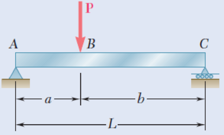
5.1 through 5.6 For the beam and loading shown, (a) draw the shear and bending-moment diagrams, (b) determine the equations of the shear and bending-moment curves.
Fig. P5.2
(a)
To draw: The shear and bending-moment diagrams.
Explanation of Solution
Determine the reactions of the beam.
Show the free-body diagram of the entire beam as in Figure 1.
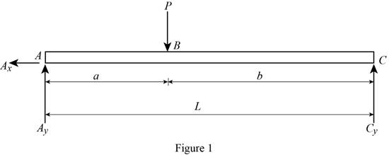
Determine the vertical reaction at point C by taking moment about point A.
Determine the vertical reaction at point A by resolving the vertical component of forces.
Substitute
Determine the horizontal direction at point A by resolving the horizontal component of forces.
Show the free-body diagram of the section 1-1 and 2-2 as in Figure 2.

Section 1-1:
Determine the shear force at the section by resolving the vertical component of forces.
Determine the moment at the section by taking moment about the section.
Section 2-2:
Determine the shear force at the section by resolving the vertical component of forces.
Determine the moment at the section by taking moment about the section.
Show the free-body diagram of the section 3-3 and 4-4 as in Figure 3.
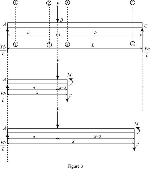
Section 3-3:
Determine the shear force at the section by resolving the vertical component of forces.
Determine the moment at the section by taking moment about the section.
When the section 3-3 is at point B,
Section 4-4:
Determine the shear force at the section by resolving the vertical component of forces.
Determine the moment at the section by taking moment about the section.
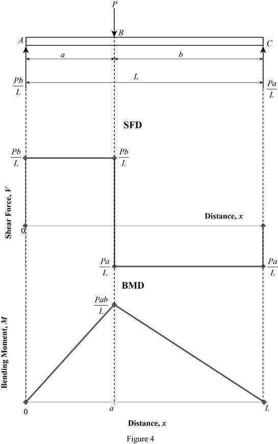
Shear force and bending moment values:
Show the calculated shear force and bending moment values as in Table 1.
| Location (x) | Shear force (V) | Bending Moment (M) |
| 1-1 | 0 | |
| 2-2 | ||
| 3-3 | ||
| 4-4 | 0 |
Plot the shear force and bending moment diagrams as in Figure 4.
(b)
The equations of the shear and bending-moment curves.
Answer to Problem 2P
The equation of shear force and bending-moment curves is:
For section AB;
For section BC;
Explanation of Solution
Determine the reactions of the beam.
Show the free-body diagram of the entire beam as in Figure 5.

Determine the vertical reaction at point C by taking moment about point A.
Determine the vertical reaction at point A by resolving the vertical component of forces.
Substitute
Determine the horizontal direction at point A by resolving the horizontal component of forces.
Show the free-body diagram of the section 1-1 and 2-2 as in Figure 6.
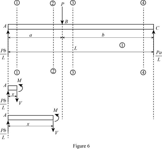
Section 1-1:
Determine the shear force at the section by resolving the vertical component of forces.
Determine the moment at the section by taking moment about the section.
Section 2-2:
Determine the shear force at the section by resolving the vertical component of forces.
Determine the moment at the section by taking moment about the section.
Show the free-body diagram of the section 3-3 and 4-4 as in Figure 7.

Section 3-3:
Determine the shear force at the section by resolving the vertical component of forces.
Determine the moment at the section by taking moment about the section.
When the section 3-3 is at point B,
Section 4-4:
Determine the shear force at the section by resolving the vertical component of forces.
Determine the moment at the section by taking moment about the section.
Therefore, the equation of shear force and bending-moment curves is:
For section AB;
For section BC;
Want to see more full solutions like this?
Chapter 5 Solutions
EBK MECHANICS OF MATERIALS


- Qu 4 The 12-kg slender rod is attached to a spring, which has an unstretched length of 2 m. If the rod is released from rest when 0 = 30°, determine its angular velocity at the instant 0 = 90°. 2 m B k = 40 N/m 2 marrow_forwardCORRECT AND DETAILED HANDWRITTEN SOLUTION WITH FBD ONLY. I WILL UPVOTE THANK YOU. CORRECT ANSWER IS ALREADY PROVIDED. 13: A cantilever beam is of length 1.5 m,loaded by a concentrated load P at its tip as shown inFig. 8-18(a), and is of circular cross section (R = 100 mm),having two symmetrically placed longitudinal holes asindicated. The material is titanium alloy, having anallowable working stress in bending of 600 MPa.Determine the maximum allowable value of the verticalforce P. ANS: P = 236,589.076 N = 236.589 kNarrow_forwardCORRECT AND DETAILED HANDWRITTEN SOLUTION WITH FBD ONLY. I WILL UPVOTE THANK YOU. CORRECT ANSWER IS ALREADY PROVIDED. 15: Consider a beam having an I-type cross section as shown in Fig. 8-45. Ashearing force V of 150 kN acts over the section. Determine the maximum and minimumvalues of the shearing stress in the vertical web of the section.ANS: fv(max) = 44.048 MPa ; fv(min) = 33.202 MPaarrow_forward
- CORRECT AND DETAILED HANDWRITTEN SOLUTION WITH FBD ONLY. I WILL UPVOTE THANK YOU. CORRECT ANSWER IS ALREADY PROVIDED. 12: A steel cantilever beam 16 ft 8 in in length is subjected to a concentrated load of 320 lb acting at the freeend of the bar. A commercially available rolled steel section, designated as W12x32, is used for the beam. Assume that the total depth of the beam is 12 in, and the neutral axis of the section is in the middle. Determine the maximum tensile and compressive stresses. (Properties of commercially available rolled steel section provided in the table. Z = section modulus). ANS: σT = σC = 1,572.482 lb/in2arrow_forwardCORRECT AND DETAILED HANDWRITTEN SOLUTION WITH FBD ONLY. I WILL UPVOTE THANK YOU. CORRECT ANSWER IS ALREADY PROVIDED. 14: Two ½-in x 8-in cover plates are welded to two channels 10 in high to formthe cross section of the beam shown in Fig. 8-59. Loads are in a vertical plane and bendingtakes place about a horizontal axis. The moment of inertia of each channel about ahorizontal axis through the centroid is 78.5 in4. If the maximum allowable elastic bendingstress is 18,000 lb/in2, determine the maximum bending moment that may be developedin the beam.ANS: 1,236,000 lb-in.arrow_forwardCORRECT AND DETAILED HANDWRITTEN SOLUTION WITH FBD ONLY. I WILL UPVOTE THANK YOU. CORRECT ANSWER IS ALREADY PROVIDED. 11: A beam of circular cross section is 7 in in diameter. It is simply supported at each end and loaded by twoconcentrated loads of 20,000 lb each, applied 12 in from the ends of the beam. Determine the maximum bending stressin the beam. ANS: σ = 7,127.172 lb/in2arrow_forward
- using the theorem of three moments, find all the reactions and supportsarrow_forward(An ellipsoidal trapping region for the Lorenz equations) Show that there is a certain ellipsoidal region E of the form rx2 + σy2 + σ(z − 2r)2 ≤ C such that all trajectories of the Lorenz equations eventually enter E and stay in there forever. For a much stiffer challenge, try to obtain the smallest possible value of C with this property.arrow_forwardA) In a factory, an s-type pitot tube was used to calculate the velocity of dry air for a point inside a stack. Calculate the velocity at that point (ft/sec) using following conditions: ● • • Pressure = 30.23 ± 0.01 in Hg (ambient) Pitot tube coefficient = 0.847 ± 0.03 Temperature = 122 ± 0.1 F (stack) Temperature = 71.2 ± 0.1 F (ambient) AP = 0.324 ± 0.008 in H2O (pitot tube) • AP = 0.891 ± 0.002 in H2O (stack) B) Find the dominant error(s) when determining precision for the problem. C) For part A, what is the precision in ft/sec for the velocity?arrow_forward
- Q1/ For what value of x do the power series converge: 8 (-1)n-1. x2n-1 2n-1 x3 x5 = X n=1 3 Q2/ Find the Interval of convergence and Radius of convergence of the series: 8 n Σ 3+1 n=1 (x)"arrow_forwardExample-1: l D A uniform rotor of length 0.6 m and diameter 0.4 m is made of steel (density 7810 kg/m³) is supported by identical short bearings of stiffness 1 MN/m in the horizontal and vertical directions. If the distance between the bearings is 0.7 m, determine the natural frequencies and plot whirl speed map. Solution: Barrow_forwardfind the laplace transform for the flowing function 2(1-e) Ans. F(s)=- S 12) k 0 Ans. F(s)= k s(1+e) 0 a 2a 3a 4a 13) 2+ Ans. F(s)= 1 s(1+e") 3 14) f(t)=1, 0arrow_forwardarrow_back_iosSEE MORE QUESTIONSarrow_forward_ios
 Elements Of ElectromagneticsMechanical EngineeringISBN:9780190698614Author:Sadiku, Matthew N. O.Publisher:Oxford University Press
 Mechanics of Materials (10th Edition)Mechanical EngineeringISBN:9780134319650Author:Russell C. HibbelerPublisher:PEARSON
 Thermodynamics: An Engineering ApproachMechanical EngineeringISBN:9781259822674Author:Yunus A. Cengel Dr., Michael A. BolesPublisher:McGraw-Hill Education
 Control Systems EngineeringMechanical EngineeringISBN:9781118170519Author:Norman S. NisePublisher:WILEY
 Mechanics of Materials (MindTap Course List)Mechanical EngineeringISBN:9781337093347Author:Barry J. Goodno, James M. GerePublisher:Cengage Learning
 Engineering Mechanics: StaticsMechanical EngineeringISBN:9781118807330Author:James L. Meriam, L. G. Kraige, J. N. BoltonPublisher:WILEY