
Videos
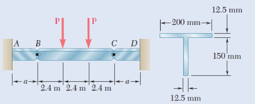
Beams AB, BC, and CD have the cross section shown and are pin-connected at B and C. Knowing that the allowable normal stress is +110 MPa in tension and –150 MPa in compression, determine (a) the largest permissible value of P if beam BC is not to be overstressed, (b) the corresponding maximum distance a for which the cantilever beams AB and CD are not overstressed.
Fig. P5.90
(a)
The largest permissible value of P for the condition that the beam BC is not overstressed.
Answer to Problem 90P
The largest permissible value of P is
Explanation of Solution
Given information:
The allowable normal stress of the material in tension is
The allowable normal stress of the material in compression is
Calculation:
Show the free-body diagram of the section BC as in Figure 1.
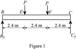
Determine the vertical reaction at point C by taking moment about point B.
Determine the vertical reaction at point B by resolving the vertical component of forces.
Show the free-body diagram of the section AB as in Figure 2.
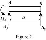
Determine the vertical reaction at point A by resolving the vertical component of forces.
Determine the moment at point A by taking moment about the point A.
Show the free-body diagram of the section CD as in Figure 3.
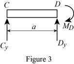
Determine the vertical reaction at point D by resolving the vertical component of forces.
Determine the moment at point D by taking moment about the point D.
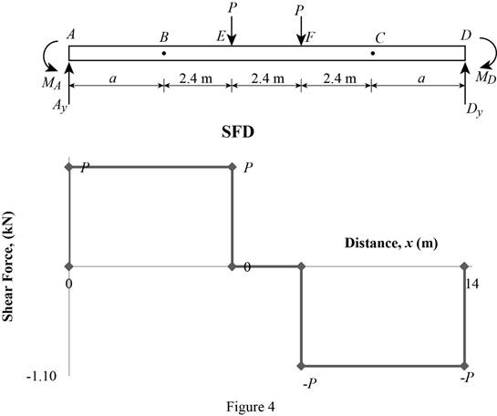
Shear force:
Show the calculation of shear force as follows;
Show the calculated shear force values as in Table 1.
| Location (x) m | Shear force (V) kN |
| A | P |
| E (Left) | P |
| E (Right) | 0 |
| F (Left) | 0 |
| F (Right) | –P |
| D | –P |
Plot the shear force diagram as in Figure 4.
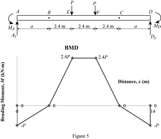
Bending moment:
Show the calculation of the bending moment as follows;
Show the calculated bending moment values as in Table 2.
| Location (x) m | Bending moment (M) kN-m |
| A | Pa |
| B | 0 |
| E | 2.4P |
| F | 2.4P |
| C | 0 |
| D | –Pa |
Plot the bending moment diagram as in Figure 5.
Show the free-body diagram of the T-section as in Figure 6.
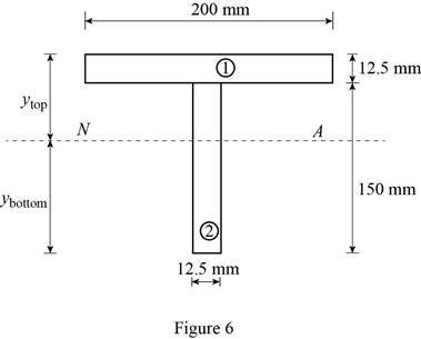
Determine the centroid in y-axis
Here, the area of the section 1 is
Refer to Figure 4;
Substitute
Determine the moment of inertia (I) using the equation.
Here, the depth of the section 1 is
Substitute 12.5 mm for
Refer to Figure 4;
Tension at Points B and D:
Refer to Figure 5;
Determine the moment at points B and D using the relation.
Substitute 110 MPa for
Compression at Points B and C:
Refer to Figure 5;
Determine the moment at points B and D using the relation.
Substitute –150 MPa for
Tension at maximum bending moment:
Refer to Figure 5;
Determine the maximum moment using the relation.
Substitute 110 MPa for
Compression at maximum bending moment:
Refer to Figure 5;
Determine the maximum moment using the relation.
Substitute –150 MPa for
Refer to the calculated distribution loads; the smallest value controls the design.
Refer to Figure 5;
Equate the maximum bending moment calculated and the maximum bending moment in the tension side.
Therefore, the largest permissible value of P for the condition that the beam BC is not overstressed is
(b)
The maximum distance a for the condition that the beams AB and CD are not overstressed.
Answer to Problem 90P
The maximum distance a for the condition that the beams AB and CD are not overstressed is
Explanation of Solution
Refer to Part (a), Figure 4;
The maximum bending moment in the beams AB and CD occurs at the ends A and D.
The calculated maximum bending moment at the points A and D is as follows:
The maximum allowable compression moment at the points A and D is as follows:
Equate the values;
Refer to the answer of the part (a);
Substitute 4.01 kN for P.
Therefore, the maximum distance a for the condition that the beams AB and CD are not overstressed is
Want to see more full solutions like this?
Chapter 5 Solutions
EBK MECHANICS OF MATERIALS


- (read image) (answer given)arrow_forward11-5. Compute all the dimensional changes for the steel bar when subjected to the loads shown. The proportional limit of the steel is 230 MPa. 265 kN 100 mm 600 kN 25 mm thickness X Z 600 kN 450 mm E=207×103 MPa; μ= 0.25 265 kNarrow_forwardT₁ F Rd = 0.2 m md = 2 kg T₂ Tz1 Rc = 0.4 m mc = 5 kg m = 3 kgarrow_forward
- 2. Find a basis of solutions by the Frobenius method. Try to identify the series as expansions of known functions. (x + 2)²y" + (x + 2)y' - y = 0 ; Hint: Let: z = x+2arrow_forward1. Find a power series solution in powers of x. y" - y' + x²y = 0arrow_forward3. Find a basis of solutions by the Frobenius method. Try to identify the series as expansions of known functions. 8x2y" +10xy' + (x 1)y = 0 -arrow_forward
- Hello I was going over the solution for this probem and I'm a bit confused on the last part. Can you please explain to me 1^4 was used for the Co of the tubular cross section? Thank you!arrow_forwardBlood (HD = 0.45 in large diameter tubes) is forced through hollow fiber tubes that are 20 µm in diameter.Equating the volumetric flowrate expressions from (1) assuming marginal zone theory and (2) using an apparentviscosity for the blood, estimate the marginal zone thickness at this diameter. The viscosity of plasma is 1.2 cParrow_forwardQ2: Find the shear load on bolt A for the connection shown in Figure 2. Dimensions are in mm Fig. 2 24 0-0 0-0 A 180kN (10 Markarrow_forward
- determine the direction and magnitude of angular velocity ω3 of link CD in the four-bar linkage using the relative velocity graphical methodarrow_forwardFour-bar linkage mechanism, AB=40mm, BC=60mm, CD=70mm, AD=80mm, =60°, w1=10rad/s. Determine the direction and magnitude of w3 using relative motion graphical method. A B 2 3 77777 477777arrow_forwardFour-bar linkage mechanism, AB=40mm, BC=60mm, CD=70mm, AD=80mm, =60°, w1=10rad/s. Determine the direction and magnitude of w3 using relative motion graphical method. A B 2 3 77777 477777arrow_forward
 Elements Of ElectromagneticsMechanical EngineeringISBN:9780190698614Author:Sadiku, Matthew N. O.Publisher:Oxford University Press
 Mechanics of Materials (10th Edition)Mechanical EngineeringISBN:9780134319650Author:Russell C. HibbelerPublisher:PEARSON
 Thermodynamics: An Engineering ApproachMechanical EngineeringISBN:9781259822674Author:Yunus A. Cengel Dr., Michael A. BolesPublisher:McGraw-Hill Education
 Control Systems EngineeringMechanical EngineeringISBN:9781118170519Author:Norman S. NisePublisher:WILEY
 Mechanics of Materials (MindTap Course List)Mechanical EngineeringISBN:9781337093347Author:Barry J. Goodno, James M. GerePublisher:Cengage Learning
 Engineering Mechanics: StaticsMechanical EngineeringISBN:9781118807330Author:James L. Meriam, L. G. Kraige, J. N. BoltonPublisher:WILEY