
Principles Of Electric Circuits
10th Edition
ISBN: 9780134879482
Author: Floyd, Thomas L.
Publisher: Pearson,
expand_more
expand_more
format_list_bulleted
Concept explainers
Videos
Textbook Question
Chapter 5, Problem 58P
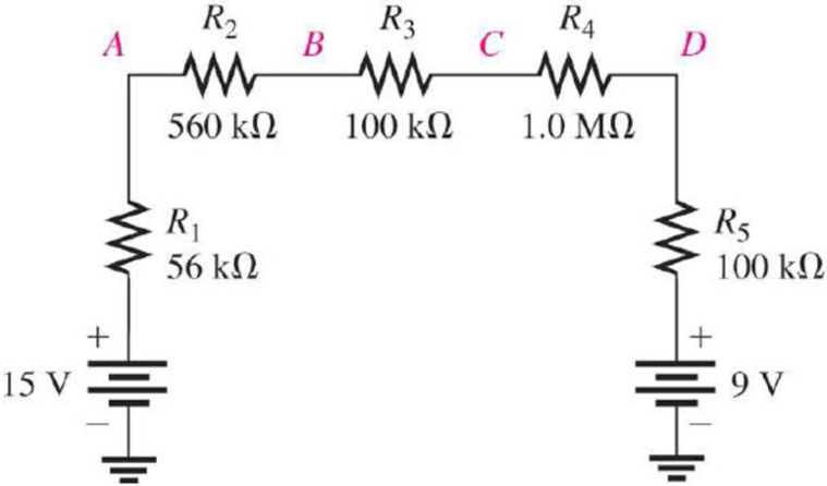
In Figure 5–89, what is VAC?
Expert Solution & Answer
Want to see the full answer?
Check out a sample textbook solution
Students have asked these similar questions
Can you show why the answer is that for this question using second order differential equations, instead of laplace transforms
2. For each of the following transfer functions,
G(s) = Y(s)/U(s), find the differential equation
relating the input u(t) to the output y(t).
(s+2)(s+3)
(a) G(s) =
(s+1)(s+4)
(s²+0.4s+1.04) (s+3)
(b) G(s)=
(s2+0.2s+1)(s+2)(s+4)
Don't use ai to answer I will report you answer
Chapter 5 Solutions
Principles Of Electric Circuits
Ch. 5 - (a) Show how you would rewire the protoboard in...Ch. 5 - How is the circuit changed when pin 2 and pin 3 in...Ch. 5 - Determine the total resistance in Figure 5-10(a)...Ch. 5 - What is the total resistance for the following...Ch. 5 - Determine the value of R4 in Figure 5-12 if the...Ch. 5 - Find RT for three 1.0 k resistors and two 720 ...Ch. 5 - What is the value of R2 if the highest current is...Ch. 5 - Determine V3 if the polarity of VS2 is reversed in...Ch. 5 - Starting with Equation 5-5, prove that the...Ch. 5 - What is the power in the circuit of Figure 5-48 if...
Ch. 5 - Determine the minimum power rating required for...Ch. 5 - Assume that R1 is shorted In Figure 5-61. What...Ch. 5 - A series circuit can have more than one path for...Ch. 5 - The total resistance of a series circuit can be...Ch. 5 - If two series resistors are different sizes, the...Ch. 5 - If two series resistors are different sizes, the...Ch. 5 - If three equal resistors are used in a voltage...Ch. 5 - There is no valid electrical reason for installing...Ch. 5 - Kirchhoffs voltage law is valid only if a loop...Ch. 5 - Prob. 8TFQCh. 5 - Prob. 9TFQCh. 5 - If point A in a circuit has a voltage of +10 V and...Ch. 5 - Two equal-value resistors are connected in series...Ch. 5 - Prob. 2STCh. 5 - Prob. 3STCh. 5 - When one of four series resistors is removed from...Ch. 5 - Prob. 5STCh. 5 - A 9 V battery is connected across a series...Ch. 5 - While putting four 1.5 V batteries in a four-cell...Ch. 5 - If you measure all the voltage drops and the...Ch. 5 - There are six resistors in a given series circuit...Ch. 5 - A series circuit consists of a 4.7 k, a 5.6 k, and...Ch. 5 - Which of the following series combinations...Ch. 5 - The total power in a certain circuit is 1 W. Each...Ch. 5 - When you connect an ammeter in a series-resistive...Ch. 5 - While checking out a series-resistive circuit, you...Ch. 5 - With a 10 V voltage source connected between...Ch. 5 - For the conditions described in Question 1, the...Ch. 5 - When the switches are in position 1 and a short...Ch. 5 - When the switches are in position 2 and a short...Ch. 5 - If the current shown by one of the milliammeters...Ch. 5 - If the source voltage decreases, the current...Ch. 5 - If the current through R1 increases as a result of...Ch. 5 - If the switch is thrown from position A to...Ch. 5 - If the switch is thrown from position B to...Ch. 5 - If the switch is thrown from position C to...Ch. 5 - If R1 is changed to 1.2 k, the voltage from A to B...Ch. 5 - If R2 and R3 are interchanged, the voltage from A...Ch. 5 - If the source voltage increases from 8 V to 10 V,...Ch. 5 - Connect each set of resistors in Figure 563 in...Ch. 5 - Determine the groupings of resistors in Figure 564...Ch. 5 - Determine the nominal resistance between pins 1...Ch. 5 - Determine the nominal resistance between pins 2...Ch. 5 - On the double-sided PC board in Figure 565,...Ch. 5 - Prob. 6PCh. 5 - Prob. 7PCh. 5 - Calculate RT for each circuit of Figure 566....Ch. 5 - What is the total resistance of twelve 5.6 k...Ch. 5 - Six 56 resistors, eight 100 resistors, and two...Ch. 5 - Prob. 11PCh. 5 - You have the following resistor values available...Ch. 5 - Find the total resistance in Figure 566 if all...Ch. 5 - What is the total resistance from A to B for each...Ch. 5 - What is the current through each resistor in a...Ch. 5 - The current from the source in Figure 569 is 5 mA....Ch. 5 - Show how to connect a voltage source and an...Ch. 5 - Using 1.5 V batteries, a switch, and three lamps,...Ch. 5 - What is the current in each circuit of Figure 570?...Ch. 5 - Determine the voltage drop across each resistor in...Ch. 5 - Three 470 resistors are connected in series with...Ch. 5 - Four equal-value resistors are in series with a 5...Ch. 5 - What is the value of each resistor in Figure 571?...Ch. 5 - Determine VR1, R2, and R3 in Figure 5-72. Figure...Ch. 5 - For the circuit in Figure 573 the meter reads 7.84...Ch. 5 - Determine the current measured by the meter in...Ch. 5 - Refer to Figure 5-75. Assume the green LED drops...Ch. 5 - Refer to Figure 5-76. Assume there is a 2.0 V drop...Ch. 5 - Series aiding is a term sometimes used to describe...Ch. 5 - The term series opposing means that sources are in...Ch. 5 - Determine the total source voltage in each circuit...Ch. 5 - Prob. 32PCh. 5 - Five resistors are in series with a 20 V source....Ch. 5 - Determine the unspecified voltage drop(s) in each...Ch. 5 - In the circuit of Figure 5-79, determine the...Ch. 5 - Find R1, R2, and R3 in Figure 580. Figure 580Ch. 5 - Determine the voltage across R5 for each position...Ch. 5 - The total resistance of a circuit is 560 . What...Ch. 5 - Determine the voltage between points A and B in...Ch. 5 - Determine the voltage with respect to ground for...Ch. 5 - Determine the minimum and maximum voltage from the...Ch. 5 - What is the voltage across each resistor in Figure...Ch. 5 - Prob. 44PCh. 5 - If there are 10 V across R1 in Figure 5-86, what...Ch. 5 - Prob. 46PCh. 5 - Prob. 47PCh. 5 - Five series resistors each handle 50 mW. What is...Ch. 5 - If you double the voltage across a resistor, by...Ch. 5 - If the total resistance of a circuit is halved,...Ch. 5 - What is the total power in the circuit in Figure...Ch. 5 - The following W resistors are in series: 1.2 k,...Ch. 5 - Find RT in Figure 587.Ch. 5 - A certain series circuit consists of a W...Ch. 5 - Determine the voltage at each point with respect...Ch. 5 - In Figure 589, how would you determine the voltage...Ch. 5 - Determine the voltage at each point with respect...Ch. 5 - In Figure 589, what is VAC?Ch. 5 - In Figure 589, what is VCA?Ch. 5 - A string of five series resistors is connected...Ch. 5 - By observing the meters in Figure 590, determine...Ch. 5 - What current would you measure in Figure 590(b) if...Ch. 5 - Table 52 shows the results of resistance...Ch. 5 - You measure 15 k between pins 5 and 6 on the PC...Ch. 5 - In checking out the PC board in Figure 591, you...Ch. 5 - The three groups of series resistors on the PC...
Knowledge Booster


Learn more about
Need a deep-dive on the concept behind this application? Look no further. Learn more about this topic, electrical-engineering and related others by exploring similar questions and additional content below.Similar questions
- 5. A schematic diagram of a motor connected to a load by gears is shown. Both the motor and the load are modeled as rotating masses with viscous damping. Find the transfer functions Øm/Tm and ØL/Tm. bm Jm Tm 0m N₂ N₁ OL но JL b₁arrow_forward3. Find the transfer function X2/F of the mechanical system in Figure. Κι www b₁ M₁ K2 www M2 b2 X2 F b3arrow_forwardS1(t) Es/Ts 0 S3(t) 0 Es/Ts Ts t S2(t) Es/Ts 0 Es/Ts Ts |7|2 S4(t) Es/Ts t Ts t 0 Ts Ts Ts Es/TS 2 1/ Q1(t) 42(t) Ts 1JT 0 t 0 Ts Ts 2 32 FIGURE 7.3 Set of signals and orthonormal functions for Example 7.1. 53(t)=√√Esq₁(t) S4(t)=-√E542(t) t Tsarrow_forward
- 1. For each of the following differential equations, determine the transfer function Y/U. Determine if the transfer function is proper or strictly proper. is not strictly proper, determine the strictly proper part. If it (a) y(3) = -3y(2) - 3y(1) — 2y + u(2) — - (b) y(3)=-3.5y(2) — 3.5y(1) — y +u(3) — 3.5u(2) + 3.5u(¹) + 3uarrow_forward.4. Find the transfer function Ø2/T of the mechanical system in Figure. TG K 02 b₁ b₂ b3arrow_forwardMatlab problem: 1) A BFSK signal is transmitted through a channel with AWGN. Generate similar BFSK received signal plots as shown below. (20 pts) BFSK for eb=1 and npower=0.01 with 500 samples BFSK for eb=1 and npower=0.1 with 500 samples 2.5 2.5 2 1.5 1 0.5 0 -0.5 -1 2 1.5 1 0.5 0.5 -1 -1.5 1.5 -1.5 -1 -0.5 0 0.5 1.5 2 2.5 -1.5 -0.5 0 0.5 1 1.5 2 2.5arrow_forward
- example 7.1 question EXAMPLE 7.1Consider the signals s1(t), s2(t), s3(t), and s4(t) shown in Figure 7.3. Using the Gram-Schmidt orthogonalization procedure, determine a set of orthonormal basis functions.Using the waveforms derived and shown in Example 7.1:a) Sketch the simplified block diagram of the transmitter and receiver as shown in figure 7.2b) Estimate the receive voltages for each transmit signal and for each branch in the receiver.arrow_forwardEXAMPLE 7.2 Consider the two equally-likely signals s₁ (t) and s2(t) that are transmitted, over an AWGN channel with the noise power spectral density of No/2, to represent bits 1 and 0, where we have: S1(t)=-S2(t)=√√2 exp(-2t)u(t) The receiver makes its decision solely based on observation of the received signal over a restricted interval of interest. Determine the average bit error rate in terms of Q-function, assuming the interval is [0,3]. Contrast numerically with the performance of an optimum receiver that observes. all the received signal, i.e., the interval of interest is (-∞, ∞).arrow_forward1) Compute the voltages at each receiver branch (Vo ad V₁ see block diagram next page) for each of the possible transmitted signals: Transmitted signals are generated as shown below: Binary wave in unipolar form (a) With basis functions: Inverter 41(t) Product modulator Product modulator 42(t) BFSK + signal + Si(t) P1(t)= √Eb = cos (2лfit+0₁) $2(t) 42(t)= √Eb 层 cos (2лf2t+ t+02) Generating signals: 2E Si(t) cos (2лfit+0₁), bit=0 Ть SBFSK (t) 2E |$2(t)= cos (2лf2t+02), bit=1arrow_forward
- Find the disruptive voltage and visual corona voltage for 3-phase line consisting of 2.5 cm diameter conductor spaced equilateral triangular formation of 4 m. The following data can be assumed, temperature 25°c, pressure 73 cm of mercury, surface factor 0.84, irregularity factor 0.72.arrow_forwardA 3-phase, 4-wire distributor supplies a balanced voltage of 400/230 V to a load consisting of 8 A at p.f. 0-7 lagging for R-phase, 10 A at p.f. 0-8 leading for Y phase and 12 A at unity p.f. for B phase. The resistance of each line conductor is 0.4 2. The reactance of neutral is 0.2 2. Calculate the neutral current, the suppl voltage for R phase and draw the phasor diagram. The phase sequence is RYB. VR Phasor diagramarrow_forwardThe three line leads of a 400/230 V, 3-phase, 4-wire supply are designated as R, Y and B respectively. The fourth wire or neutral wire is designated as N. The phase sequence is RYB. Compute the currents in the four wire when the following loads are connected to this supply: From R to N: 25 kW, unity power facto. From Y to N: 20 kVA, 0-7 lag. From B to N: 30 kVA, 0-6 lead.arrow_forward
arrow_back_ios
SEE MORE QUESTIONS
arrow_forward_ios
Recommended textbooks for you
 Electricity for Refrigeration, Heating, and Air C...Mechanical EngineeringISBN:9781337399128Author:Russell E. SmithPublisher:Cengage Learning
 Delmar's Standard Textbook Of ElectricityElectrical EngineeringISBN:9781337900348Author:Stephen L. HermanPublisher:Cengage Learning
Electricity for Refrigeration, Heating, and Air C...
Mechanical Engineering
ISBN:9781337399128
Author:Russell E. Smith
Publisher:Cengage Learning
Delmar's Standard Textbook Of Electricity
Electrical Engineering
ISBN:9781337900348
Author:Stephen L. Herman
Publisher:Cengage Learning
Nodal Analysis for Circuits Explained; Author: Engineer4Free;https://www.youtube.com/watch?v=f-sbANgw4fo;License: Standard Youtube License