
Principles Of Electric Circuits
10th Edition
ISBN: 9780134879482
Author: Floyd, Thomas L.
Publisher: Pearson,
expand_more
expand_more
format_list_bulleted
Concept explainers
Videos
Textbook Question
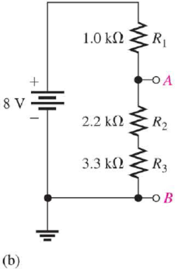
Chapter 5, Problem 13CDQ
If the source voltage increases from 8 V to 10 V, the voltage from A to B
- a. increases
- b. decreases
- c. stays the same
Expert Solution & Answer
Want to see the full answer?
Check out a sample textbook solution
Students have asked these similar questions
Matched filter in the frequency domain
(1.5) (a) Consider the signal s(t) in 3(c). Assuming that the unit of time is a millisecond
and the desired frequency resolution is 1 Hz, use the function contFT to compute
and plot |S(f).
(b) Use the function contFT to compute and plot the magnitude of the Fourier trans-
form of the convolution s * SMF numerically computed in 3(d). Also plot for
comparison |S(f)12, using the output of 5(a). The two plots should match.
(c) Plot the phase of the Fourier transform of s✶ SMF obtained in 5(b). Comment on
whether the plot matches your expectations.
Find Eigenvalues and Eigenvectors for the following matrices:
[10
4
A=0
2
0
3
1
1 -3
1. (20 pts) Plot the pulse and the FFT for a pulse with the following properties at x=0 and x=10
cm.
f=2 MHz
m=3
Ncyc=2, 6, 20
po 1 MPa (source pressure)
x=10 cm (propagates in a Newtonian fluid for 10 cm as a plane wave-not a sound beam)
a=0.5 dB/(MHz cm)
Consider 3 types of waves: sine, square, and sawtooth. (square and sawtooth only for grad
students)
Observe your plots and draw some conclusions. Discuss any possible issues you encounter.
2. (20 pts) We have the following 3 ultrasonic transducers:
a. Focused 1 MHz, 2.54 cm diameter, 5.08 cm focus
b. Focused 3 MHz, 2.54 cm diameter, 5.08 cm focus
c. Unfocused 0.1 MHz, 2.54 cm diameter
The transducers are operating in water (c=1486 m/s).
I. Plot the axial field for all transducers
II. Plot the focal transverse field for the focused transducers and the transverse field at the
Rayleigh distance (R_0) and at 2R_0 for the unfocused.
III. Assume source pressure of 0.1 MPa, and find the acoustic pressure in MPa at the location
(r=0, z=4.5…
Chapter 5 Solutions
Principles Of Electric Circuits
Ch. 5 - (a) Show how you would rewire the protoboard in...Ch. 5 - How is the circuit changed when pin 2 and pin 3 in...Ch. 5 - Determine the total resistance in Figure 5-10(a)...Ch. 5 - What is the total resistance for the following...Ch. 5 - Determine the value of R4 in Figure 5-12 if the...Ch. 5 - Find RT for three 1.0 k resistors and two 720 ...Ch. 5 - What is the value of R2 if the highest current is...Ch. 5 - Determine V3 if the polarity of VS2 is reversed in...Ch. 5 - Starting with Equation 5-5, prove that the...Ch. 5 - What is the power in the circuit of Figure 5-48 if...
Ch. 5 - Determine the minimum power rating required for...Ch. 5 - Assume that R1 is shorted In Figure 5-61. What...Ch. 5 - A series circuit can have more than one path for...Ch. 5 - The total resistance of a series circuit can be...Ch. 5 - If two series resistors are different sizes, the...Ch. 5 - If two series resistors are different sizes, the...Ch. 5 - If three equal resistors are used in a voltage...Ch. 5 - There is no valid electrical reason for installing...Ch. 5 - Kirchhoffs voltage law is valid only if a loop...Ch. 5 - Prob. 8TFQCh. 5 - Prob. 9TFQCh. 5 - If point A in a circuit has a voltage of +10 V and...Ch. 5 - Two equal-value resistors are connected in series...Ch. 5 - Prob. 2STCh. 5 - Prob. 3STCh. 5 - When one of four series resistors is removed from...Ch. 5 - Prob. 5STCh. 5 - A 9 V battery is connected across a series...Ch. 5 - While putting four 1.5 V batteries in a four-cell...Ch. 5 - If you measure all the voltage drops and the...Ch. 5 - There are six resistors in a given series circuit...Ch. 5 - A series circuit consists of a 4.7 k, a 5.6 k, and...Ch. 5 - Which of the following series combinations...Ch. 5 - The total power in a certain circuit is 1 W. Each...Ch. 5 - When you connect an ammeter in a series-resistive...Ch. 5 - While checking out a series-resistive circuit, you...Ch. 5 - With a 10 V voltage source connected between...Ch. 5 - For the conditions described in Question 1, the...Ch. 5 - When the switches are in position 1 and a short...Ch. 5 - When the switches are in position 2 and a short...Ch. 5 - If the current shown by one of the milliammeters...Ch. 5 - If the source voltage decreases, the current...Ch. 5 - If the current through R1 increases as a result of...Ch. 5 - If the switch is thrown from position A to...Ch. 5 - If the switch is thrown from position B to...Ch. 5 - If the switch is thrown from position C to...Ch. 5 - If R1 is changed to 1.2 k, the voltage from A to B...Ch. 5 - If R2 and R3 are interchanged, the voltage from A...Ch. 5 - If the source voltage increases from 8 V to 10 V,...Ch. 5 - Connect each set of resistors in Figure 563 in...Ch. 5 - Determine the groupings of resistors in Figure 564...Ch. 5 - Determine the nominal resistance between pins 1...Ch. 5 - Determine the nominal resistance between pins 2...Ch. 5 - On the double-sided PC board in Figure 565,...Ch. 5 - Prob. 6PCh. 5 - Prob. 7PCh. 5 - Calculate RT for each circuit of Figure 566....Ch. 5 - What is the total resistance of twelve 5.6 k...Ch. 5 - Six 56 resistors, eight 100 resistors, and two...Ch. 5 - Prob. 11PCh. 5 - You have the following resistor values available...Ch. 5 - Find the total resistance in Figure 566 if all...Ch. 5 - What is the total resistance from A to B for each...Ch. 5 - What is the current through each resistor in a...Ch. 5 - The current from the source in Figure 569 is 5 mA....Ch. 5 - Show how to connect a voltage source and an...Ch. 5 - Using 1.5 V batteries, a switch, and three lamps,...Ch. 5 - What is the current in each circuit of Figure 570?...Ch. 5 - Determine the voltage drop across each resistor in...Ch. 5 - Three 470 resistors are connected in series with...Ch. 5 - Four equal-value resistors are in series with a 5...Ch. 5 - What is the value of each resistor in Figure 571?...Ch. 5 - Determine VR1, R2, and R3 in Figure 5-72. Figure...Ch. 5 - For the circuit in Figure 573 the meter reads 7.84...Ch. 5 - Determine the current measured by the meter in...Ch. 5 - Refer to Figure 5-75. Assume the green LED drops...Ch. 5 - Refer to Figure 5-76. Assume there is a 2.0 V drop...Ch. 5 - Series aiding is a term sometimes used to describe...Ch. 5 - The term series opposing means that sources are in...Ch. 5 - Determine the total source voltage in each circuit...Ch. 5 - Prob. 32PCh. 5 - Five resistors are in series with a 20 V source....Ch. 5 - Determine the unspecified voltage drop(s) in each...Ch. 5 - In the circuit of Figure 5-79, determine the...Ch. 5 - Find R1, R2, and R3 in Figure 580. Figure 580Ch. 5 - Determine the voltage across R5 for each position...Ch. 5 - The total resistance of a circuit is 560 . What...Ch. 5 - Determine the voltage between points A and B in...Ch. 5 - Determine the voltage with respect to ground for...Ch. 5 - Determine the minimum and maximum voltage from the...Ch. 5 - What is the voltage across each resistor in Figure...Ch. 5 - Prob. 44PCh. 5 - If there are 10 V across R1 in Figure 5-86, what...Ch. 5 - Prob. 46PCh. 5 - Prob. 47PCh. 5 - Five series resistors each handle 50 mW. What is...Ch. 5 - If you double the voltage across a resistor, by...Ch. 5 - If the total resistance of a circuit is halved,...Ch. 5 - What is the total power in the circuit in Figure...Ch. 5 - The following W resistors are in series: 1.2 k,...Ch. 5 - Find RT in Figure 587.Ch. 5 - A certain series circuit consists of a W...Ch. 5 - Determine the voltage at each point with respect...Ch. 5 - In Figure 589, how would you determine the voltage...Ch. 5 - Determine the voltage at each point with respect...Ch. 5 - In Figure 589, what is VAC?Ch. 5 - In Figure 589, what is VCA?Ch. 5 - A string of five series resistors is connected...Ch. 5 - By observing the meters in Figure 590, determine...Ch. 5 - What current would you measure in Figure 590(b) if...Ch. 5 - Table 52 shows the results of resistance...Ch. 5 - You measure 15 k between pins 5 and 6 on the PC...Ch. 5 - In checking out the PC board in Figure 591, you...Ch. 5 - The three groups of series resistors on the PC...
Knowledge Booster


Learn more about
Need a deep-dive on the concept behind this application? Look no further. Learn more about this topic, electrical-engineering and related others by exploring similar questions and additional content below.Similar questions
- Find the Q-points for the diodes in the circuit. Assume ideal diodes, and startwith the assumption that D is OFF, and D2 is ON for both circuits.arrow_forwardplease see the following image to answer questions thanksarrow_forward5- Find the Eigenvalues and the corresponding Eigenvectors. [4 5 31 A=0 4 6 Lo 0 1arrow_forward
- Find the Eigenvalues and the corresponding Eigenvectors. 4 2 -2 A = 2 5 0,2=4 -2 -2 0 3arrow_forward1. Label the x, y, z coordinates for each frame. 2. Compute the homogeneous transformation matrices H between frames 0, 1, 2, and end- effector.arrow_forwardFind Eigenvalues and Eigenvectors for the following matrices: 1] [5-6 A = 1 1 0 L3 0 1arrow_forward
- Use Gauss-Jordan Elimination method to solve the following system: 4x1+5x2 + x3 = 2 x1-2x2 3x3 = 7 - 3x1 x2 2x3 = 1. -arrow_forwardFind the Eigenvalues and the corresponding Eigenvectors. A = [³/2 9] 3.arrow_forwardFind the Q-points for the diodes in the circuit. Assume ideal diodes, and startwith the assumption that both diodes are ON for both circuits.arrow_forward
- I need help with the PSpice part. How do I do the PSpice stuff.arrow_forwardUse Gauss-Jordan Elimination method to solve the following system: 4x1 +5x2 + x3 = 2 x1-2x2 3x3 = 7 - 3x1 x2 2x3 = 1. -arrow_forwardNo need to solve question 1. Only work on question 2 where you make the PSpice model for this circuit. I need the basic step by step to find what is wanted in question 1. Explain what kind of analysis is used and what details are adjusted in it. Also explain/perform gathering the data on a plot for the simulation.arrow_forward
arrow_back_ios
SEE MORE QUESTIONS
arrow_forward_ios
Recommended textbooks for you
 Power System Analysis and Design (MindTap Course ...Electrical EngineeringISBN:9781305632134Author:J. Duncan Glover, Thomas Overbye, Mulukutla S. SarmaPublisher:Cengage Learning
 Electricity for Refrigeration, Heating, and Air C...Mechanical EngineeringISBN:9781337399128Author:Russell E. SmithPublisher:Cengage Learning
 Delmar's Standard Textbook Of ElectricityElectrical EngineeringISBN:9781337900348Author:Stephen L. HermanPublisher:Cengage Learning
Power System Analysis and Design (MindTap Course ...
Electrical Engineering
ISBN:9781305632134
Author:J. Duncan Glover, Thomas Overbye, Mulukutla S. Sarma
Publisher:Cengage Learning
Electricity for Refrigeration, Heating, and Air C...
Mechanical Engineering
ISBN:9781337399128
Author:Russell E. Smith
Publisher:Cengage Learning
Delmar's Standard Textbook Of Electricity
Electrical Engineering
ISBN:9781337900348
Author:Stephen L. Herman
Publisher:Cengage Learning
FMPR-103 pt1 l Power Systems Protection v1; Author: L&D for Protection and Control;https://www.youtube.com/watch?v=ELWncjsh5uE;License: Standard Youtube License