
Videos
The drag of a full-scale aircraft.
Answer to Problem 5.72P
The aircraft (full scale) has a drag of
Explanation of Solution
Given Information:
Model chord length,
Wing Area,
Velocity of full-scale aircraft,
| V, mi/h | 50 | 75 | 100 | 125 |
| Drag, N | 15 | 32 | 53 | 80 |
Drag coefficient for 1st case
Where
Similarly, drag coefficient for 2nd case
Drag coefficient for 3rd case
Drag coefficient for 4th case
Now, calculate Reynolds number for 1st case
Where L = Length of chord
Viscosity,
Reynolds number for 2nd case
Reynolds number for 3rd case
Reynolds number for 4th case
Aircraft is flying at 32800 ft at velocity
Density,
Viscosity,
Length (full scale)
Reynolds number (full scale)
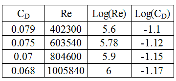
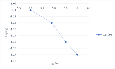
From the graph the best fit curve equation is
Let
We know,
Drag (full scale) is calculated by the below formula
Here, full scale area of the wing
Conclusion:
The aircraft (full scale) has a drag of
Want to see more full solutions like this?
Chapter 5 Solutions
Fluid Mechanics, 8 Ed


- Q. 1: The partial Routh array of a unity feedback system is given below. S6 1 Adel 8 S5 1 S4 2 Bash 6 -4 0 C 0 How many roots does it have in the right half plane? Comment on the stability of the system. Determine the characteristic equation of the system. Q.2: Find the values of Ki and K2 for the system shown in the figure below when Mp=0.25% and tp= 4 sec. assume unit step input. R(S) K₁ C(S) 1+ K₂Sarrow_forwardTemperature EXAMPLE 1: A diesel engine is fitted with a turbocharger, which comprises a radial compressor driven by a radial exhaust gas turbine. The air is drawn into the compressor at a pressure of 0.95 bar and at a temperature of 15°C, and is delivered to the engine at a pressure of 2.0 bar. The engine is operating on a gravimetric air/fuel ratio of 18: 1, and the exhaust leaves the engine at a temperature of 600°C and at a pressure of 1.8 bar; the turbine exhausts at 1.05 bar. The isentropic efficiencies of the compressor and T(K) turbine are 70 per cent and 80 per cent, respectively. Calculate (i) the temperature of the air leaving the compressor (ii) the temperature of the gases leaving the turbine (iii) the mechanical power loss in the turbocharger expressed as a percentage of the power generated in the turbine. Using the values of : Cpair = 1.01 kJ/kg K, Vair = 1.4 Cpex = 1.15 kJ/kg K, Yex = 1.33 and 2s с P2 Engine P3 W W₁ = mexpex (T3-TA) At W₁ = mair Cpex (T2-T₁) 4 P4…arrow_forwardProblem 8.28 Part A 10 of 10 ■Review The uniform crate resting on the dolly has a mass of 530 kg and mass center at G as shown in (Figure 1). If the front casters contact a high step, and the coefficient of static friction between the crate and the dolly is μs = 0.45, determine the greatest force P that can be applied without causing motion of the crate. The dolly does not move. Express your answer to three significant figures and include the appropriate units. Figure -0.5 m- 0.6 m 0.3 m 0.1 m B 0.4 m 0.3 m > ☐ P = 1210 Submit о ΜΑ N Previous Answers Request Answer × Incorrect; Try Again 1 of 1 < Return to Assignment Provide Feedback ?arrow_forward
- Q1: For the system shown in Fig. 6.7, the following data are applicable P1 = 7 bar Q=0.002 m3/sec Pipe: total length 15m and ID 38mm Oil: SG-0.90 and kinematic viscosity (v-0.0001 m2/s) Solve for P2 in units of bars. Motor OH Pump Breather P1 Pipe length = 3m 90' elbow ☐ 38 mm (ID) Pipe length = 2m P2 Load force Pipe length 4 m = Pipe length=6m 90' elbowarrow_forwardusing the three moment theorem please find the moments about B, C and Darrow_forwardA viscous fluid flows in a 0.10-m-diameter pipe such that its velocity measured 0.010 m away from the pipe wall is 0.9 m/s. If the flow is laminar, determine (a) the centerline velocity and (b) the flowrate. (a) Vi (b) Q = i m/s × 103 m³/sarrow_forward
- This is an old exam review problem. Please helparrow_forward3. The volumetric flow rate of air through a duct transition of the type shown in Table 12-9b (rectangular with two parallel sides) is 2 m3/s. The duct before the transition issquare, with a height of 50 cm. The expansion ratio across the transition is 4 (i.e., theduct area after the transition is 4 times greater than the duct area before the transition).a) Determine the pressure loss (in Pa) across the transition if the exit from the duct isabrupt (i.e., the diverging angle of the transition is 180º).b) Determine the percentage reduction in pressure loss for a transition diverging angleof 20º compared to the one in part (a).c) The head HVAC engineer requires the pressure loss across the transition to bereduced to less than 50% of the pressure loss for an abrupt exit (i.e., the case in part(a)), and suggests a transition diverging angle of 45º. Will this new diverging angleachieve the required reduction in pressure loss? Justify your answer.d) For a transition diverging angle of 90º,…arrow_forwardThe wheel shown is made of 2 rings and 8 rods. The otter ring weighs 100 lbs, the inner ring weighs 15 lbs,and each of the rods weighs 20 lbs. Find the moment of inertia of the wheel about an axis that comes directlyout of the page through point A.arrow_forward
 Elements Of ElectromagneticsMechanical EngineeringISBN:9780190698614Author:Sadiku, Matthew N. O.Publisher:Oxford University Press
 Mechanics of Materials (10th Edition)Mechanical EngineeringISBN:9780134319650Author:Russell C. HibbelerPublisher:PEARSON
 Thermodynamics: An Engineering ApproachMechanical EngineeringISBN:9781259822674Author:Yunus A. Cengel Dr., Michael A. BolesPublisher:McGraw-Hill Education
 Control Systems EngineeringMechanical EngineeringISBN:9781118170519Author:Norman S. NisePublisher:WILEY
 Mechanics of Materials (MindTap Course List)Mechanical EngineeringISBN:9781337093347Author:Barry J. Goodno, James M. GerePublisher:Cengage Learning
 Engineering Mechanics: StaticsMechanical EngineeringISBN:9781118807330Author:James L. Meriam, L. G. Kraige, J. N. BoltonPublisher:WILEY