
Concept explainers
Videos
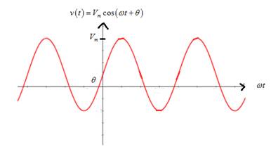
Consider the plot of the sinusoidal voltage
- Stretches the sinusoidal curve vertically.
Which statement best describes
b. Increasing the frequency f?
c. Decreasing
d. Decreasing the angular frequency w?
e. Increasing the period?
(a)
Change in sinusoidal voltage graph if peak amplitude is increased.
Answer to Problem 5.1P
Increasing the peak amplitude stretches the sinusoidal curve vertically.
Option (1).
Explanation of Solution
Given information:
Given sinusoidal voltage is
Calculation:
Graph of sinusoidal voltage is
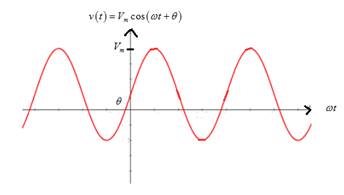
From the graph, it is noted thatif peak amplitude Vm is increased, it stretches the sinusoidal curve vertically.
(b)
Change in sinusoidal voltage graph if frequency is increased.
Answer to Problem 5.1P
Increasing the frequency compresses the sinusoidal curve horizontally.
Option (4).
Explanation of Solution
Given information:
Given sinusoidal voltage is
Calculation:
Graph of sinusoidal voltage is

From the graph, it is noted that if the frequency is increased,the time period is reduced so that it compresses the sinusoidal curve horizontally.
(c)
Change in sinusoidal voltage graph if phase angle (theta) is decreased.
Answer to Problem 5.1P
Decreasing the phase angle (theta) translates the sinusoidal curve to the right.
Option (5).
Explanation of Solution
Given information:
Given sinusoidal voltage is
Calculation:
Graph of sinusoidal voltage is

From the graph, it is noted that if the phase angle (theta) is decreased, it translates the sinusoidal curve to the right.
(d)
Change in sinusoidal voltage graph if the angular frequency is decreased.
Answer to Problem 5.1P
Decreasing the angular frequency stretches the sinusoidal voltage graph horizontally.
Option (3).
Explanation of Solution
Given information:
Given sinusoidal voltage is
Calculation:
Graph of sinusoidal voltage is
From the graph, it is noted that if the angular frequency is decreased, it increases the time period of the curve,which means it stretches sinusoidal horizontally.
(e)
Change in sinusoidal voltage graph if the time period is increased.
Answer to Problem 5.1P
Increasing the time period stretches the sinusoidal voltage graph horizontally.
Option (3).
Explanation of Solution
Given information:
Given sinusoidal voltage is
Calculation:
Graph of sinusoidal voltage is

From the graph, it is noted that if time period is increased, it stretches the sinusoidal voltage graph horizontally.
Want to see more full solutions like this?
Chapter 5 Solutions
Pearson eText for Electrical Engineering: Principles & Applications -- Instant Access (Pearson+)
Additional Engineering Textbook Solutions
Elementary Surveying: An Introduction To Geomatics (15th Edition)
Computer Science: An Overview (13th Edition) (What's New in Computer Science)
Degarmo's Materials And Processes In Manufacturing
Mechanics of Materials (10th Edition)
Introduction To Programming Using Visual Basic (11th Edition)
Java: An Introduction to Problem Solving and Programming (8th Edition)


- 10.8 In the network of Fig. P10.8, Za = Zb = Zc = (25+ j5) W.Determine the line currents.arrow_forwardUsing D flip-flops, design a synchronous counter. The counter counts in the sequence 1,3,5,7, 1,7,5,3,1,3,5,7,.... when its enable input x is equal to 1; otherwise, the counter count 0. Present state Next state x=0 Next state x=1 Output SO 52 S1 1 S1 54 53 3 52 53 S2 56 51 0 $5 5 54 S4 53 0 55 58 57 7 56 56 55 0 57 S10 59 1 58 58 S7 0 59 S12 S11 7 $10 $10 59 0 $11 $14 $13 5 $12 S12 $11 0 513 $15 SO 3 S14 $14 S13 0 $15 515 SO 0 Explain how to get the table step by step with drawing the state diagram and finding the Karnaugh map.arrow_forwardFor the oscillator resonance circuit shown in Fig. (5), derive the oscillation frequency Feedback and open-loop gains. L₁ 5 mH (a) ell +10 V R₁ ww R3 S C2 HH 1 με 1000 pF 100 pF R₂ 1 με RA H (b) +9 V R4 CA 470 pF C₁ R3 HH 1 με R₁ ww L₁ 000 1.5 mH R₂ ww Hi 1 μF L2 m 10 mHarrow_forward
- Expert handwritten solution onlyarrow_forwardB. For the oscillator circuit shown in frequency, feedback and open-loop gains. +10 V name the circuit, derive and find the oscillation P.Av +9 V -000 4₁ 5 mH w R₁ C₂ HH 1 με w 100 pF R₂ T R CA www. 470 pF w ww www 1000 pF HH 1μF C₁ HH 1μF Ra ww HI 4₁ 000 1.5 mH H 4 AF 000 10 mHarrow_forwardI want to check if the current that I have from using the mesh analysis is correct? I1 = 0.214mA I2 = -0.429mAarrow_forward
- I want to find the current by using mesh analysis pleasearrow_forwardI want to find the current by using mesh analysis pleasearrow_forwardR₁ W +10 V R3 +9 V C₂ R₁ CA C₁ 470 pF HH 1000 pF HH 1 με C4 1 μF 1 uF C₁ R₂ R4 100 pF Find Open-loop Jain L₁ 5 mH (a) Av=S,B={" H R₁₂ ✓ ww (b) R₁ L₁ 000 1.5 mH R₂ H 1 uF 12 10 mHarrow_forward
- A) Calculate the efficiency of the test transformer at the resistive loads (X-25%, 50%, 75%, 100%, 125% full load). B) From part (A) draw the plot (efficiency Vs power output) of the transformer. C) Discuss the plot of part (B).arrow_forwarda- Determine fH; and Ho b- Find fg and fr. c- Sketch the frequency response for the high-frequency region using a Bode plot and determine the cutoff frequency. Ans: 277.89 KHz; 2.73 MHz; 895.56 KHz; 107.47 MHz. 14V Cw=5pF Cwo-8pF Coc-12 pF 5.6kQ Ch. 40. pF C-8pF 68kQ 0.47µF Vo 0.82 kQ V₁ B=120 0.47µF www 3.3kQ 10kQ 1.2kQ =20µF Narrow_forwardUsing D flip-flops, design a synchronous counter. The counter counts in the sequence 1,3,5,7, 1,7,5,3,1,3,5,7,.... when its enable input x is equal to 1; otherwise, the counter. This counter is for individual settings only need the state diagram and need the state table to use 16 states from So to S15.arrow_forward
 Introductory Circuit Analysis (13th Edition)Electrical EngineeringISBN:9780133923605Author:Robert L. BoylestadPublisher:PEARSON
 Delmar's Standard Textbook Of ElectricityElectrical EngineeringISBN:9781337900348Author:Stephen L. HermanPublisher:Cengage Learning
 Programmable Logic ControllersElectrical EngineeringISBN:9780073373843Author:Frank D. PetruzellaPublisher:McGraw-Hill Education
 Fundamentals of Electric CircuitsElectrical EngineeringISBN:9780078028229Author:Charles K Alexander, Matthew SadikuPublisher:McGraw-Hill Education
 Electric Circuits. (11th Edition)Electrical EngineeringISBN:9780134746968Author:James W. Nilsson, Susan RiedelPublisher:PEARSON
 Engineering ElectromagneticsElectrical EngineeringISBN:9780078028151Author:Hayt, William H. (william Hart), Jr, BUCK, John A.Publisher:Mcgraw-hill Education,