
Find the axial force, shear force, and bending moments at points A and B of the given beam.
Answer to Problem 1P
The axial force at point A is
The shear force at point A is
The bending moment at point A is
The axial force at point B is
The shear force at point B is
The bending moment at point B is
Explanation of Solution
Given information:
The point load acting at the distance of 5 m from the left support
The inclined point load acting at the distance of 10 m from the left support
The point load acting at the distance of 15 m from the left support
Sign conversion:
Apply the sign convention for calculating the equations of equilibrium as below.
- For the horizontal forces equilibrium condition, take the force acting towards right side as positive
- For the vertical forces equilibrium condition, take the upward force as positive
- For moment equilibrium condition, take the clockwise moment as negative and counter clockwise moment as positive.
Apply the following sign convention for calculating the axial forces, shear and bending moments.
- When the portion of the beam considered is left of the section, then the external force acting to the left are considered as positive.
- When the portion of the beam considered is right of the section, then the external force acting to the right are considered as positive.
- When the portion of the beam considered is left of the section, then the external force acting upward are considered as positive.
- When the portion of the beam considered is right of the section, then the external force acting downward are considered as positive.
- When the portion of the beam considered is left of the section, then the clockwise moments are considered as positive.
- When the portion of the beam considered is right of the section, then the counterclockwise moments are considered as positive.
Calculation:
Draw the free body diagram of the entire beam as in Figure (1).
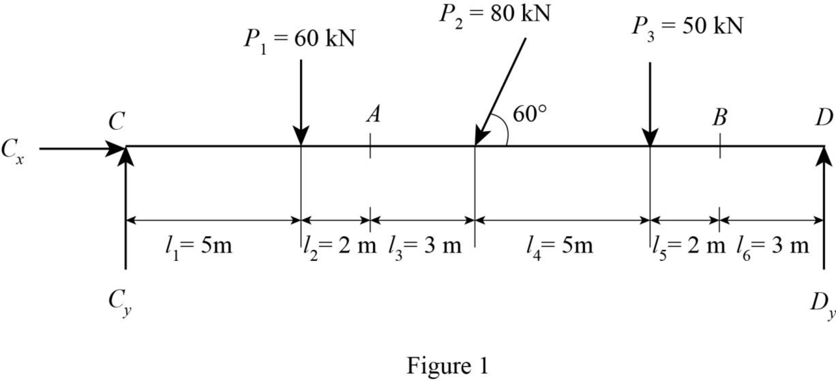
Determine the horizontal force at point C using equilibrium condition.
Substitute 80 kN for
Consider clockwise moment as positive and counter clockwise moment as negative.
Determine the vertical force at the left support using equilibrium condition.
Taking moment about point D.
Substitute 20 m for L, 60 kN for
Determine the vertical force at the right support using equilibrium condition.
Substitute 92.14 kN for
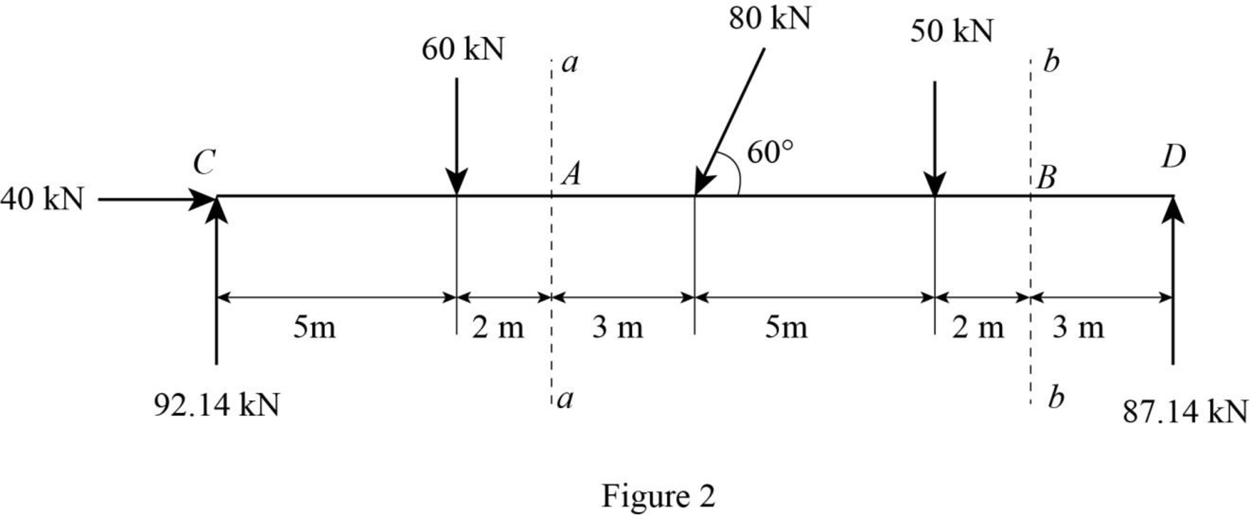
Pass the sections aa and bb at points A and B respectively.
Draw the sections aa and bb as in Figure (2).
Consider section aa.
Show the free-body diagram of the left side of the section aa as in Figure 3.
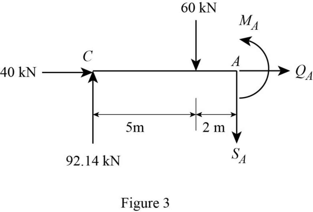
Axial force:
Consider the external forces acting to the left as positive.
Find the axial force at point A by resolving the horizontal equilibrium.
Therefore, the axial force at point A is
Shear force:
Consider the external forces acting upward as positive.
Determine the shear at point A using the relation.
Substitute 92.14 kN for
Therefore, the shear force at point A is
Bending moment:
Consider the clockwise moments of the external forces about A as positive.
Determine the moment at point A equilibrium equations.
Taking moment about point A.
Substitute 92.14 kN for
Therefore, the bending moment at point A is
Consider section bb:
Consider the right side of the section bb for calculation of internal forces.
Show the free-body diagram of the right side of the section bb as in Figure 4.
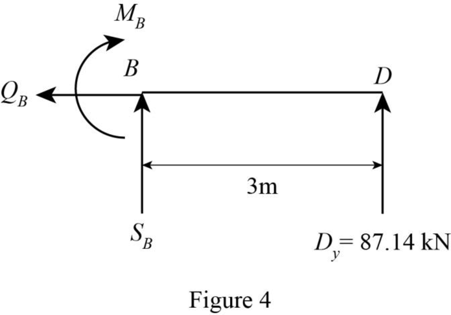
Axial force:
Find the axial force at point B by resolving the horizontal equilibrium.
Therefore, the axial force at point B is
Shear force:
Determine the shear at point B using the relation.
Substitute 87.14 kN for
Therefore, the shear force at point B is
Bending moment:
Consider the counter clockwise moments of the external forces about B as positive.
Determine the moment at point B equilibrium equations.
Taking moment about point B.
Substitute 87.14 kN for
Therefore, the bending moment at point B is
Want to see more full solutions like this?
Chapter 5 Solutions
Structural Analysis (MindTap Course List)

- B3. For the Howe truss below, assume all members are pin connected and take P₁ = 5 kN and P₂ = 10 kN: a. Determine all member forces (16 pts). b. Use a section cut to verify your answers for members GF, GD, and CD (4 Pts) P₁ A H 500 8 0000 B 0000] 2 m m 2 m 3 m B E D marrow_forwardI need detailed help solving this exercise from homework of Engineering Mathematics II.I do not really understand how to do, please do it step by step, not that long but clear. Thank you!P.S.: Please do not use AI, thanks!arrow_forwardI need detailed help solving this exercise from homework of Engineering Mathematics II.I do not really understand how to do, please do it step by step, not that long but clear. Thank you!P.S.: Please do not use AI, thanks!arrow_forward
- I need detailed help solving this exercise from homework of Engineering Mathematics II.I do not really understand how to do, please do it step by step, not that long but clear. Thank you!P.S.: Please do not use AI, thanks!arrow_forwardI need detailed help solving this exercise from homework of Engineering Mathematics II.I do not really understand how to do, please do it step by step, not that long but clear. Thank you!P.S.: Please do not use AI, thanks!arrow_forwardI need detailed help solving this exercise from homework of Engineering Mathematics II.I do not really understand how to do, please do it step by step, not that long but clear. Thank you!P.S.: Please do not use AI, thanks!arrow_forward
- I need detailed help solving this exercise from homework of Engineering Mathematics II.I do not really understand how to do, please do it step by step, not that long but clear. Thank you!P.S.: Please do not use AI, thanks!arrow_forwardI need detailed help solving this exercise from homework of Engineering Mathematics II.I do not really understand how to do, please do it step by step, not that long but clear. Thank you!P.S.: Please do not use AI, thanks!arrow_forwardI need detailed help solving this exercise from homework of Engineering Mathematics II.I do not really understand how to do, please do it step by step, not that long but clear. Thank you!P.S.: Please do not use AI, thanks!arrow_forward
- B1.For the truss below, take P₁ = 4 kip and P₂ = 3 kip: a. Determine all member forces. Hint: first find zero-force members (16 pts). b. Use a section cut to verify your answers for members JI, BI, and BC (4 Pts) В 18 ft 6 ft H B 6 ft C 8 ft D p81 8 ft E 8 ft 6 ft F6ftarrow_forwardQ13: The line CD, C(xc, 6), D(6,yd), the point D is on the right of point C, the value of horizontal effect H(3,0) is on the right of point C, the vertical effect V(0, -2) right of H. the distance between projection of the points H, V is 5cm, Find: 1- The value of xc and yd. 2- The distance between projections of the points C, D. 3- The true length (T.L.) of CD. 4- The angles a and ẞ. 5- A point F in the middle of line CD, find F (xf, yf).arrow_forwardQ9: The straight line AB of true length (8) cm, having the following data: A (5, ya) & B (xb, yb), the point B is on the left of point A, the inclination of the line to the horizontal plane (H.P) is 30° (a) it Horizontal trace H (-3, 0), and point H is on the left of point A with distance (16) cm. Draw the Plan & Elevation of the line AB and determine the following: 1. The missed coordinates: ya, xb, yb. 2. The coordinates of the vertical trace (V). 3. The inclination of the line to the vertical plane (V.P) (B). 4. The distance between projections of the points A and Barrow_forward
