
Concept explainers
Videos
(a)
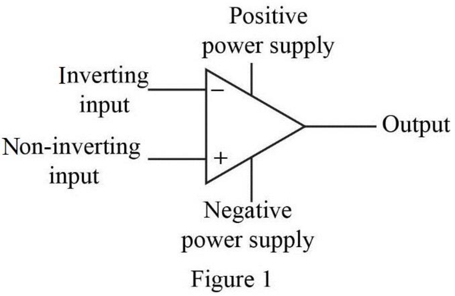
Label the five terminals in the operational amplifier.
(a)
Explanation of Solution
Given data:
Refer to Figure P5.1 in the textbook for the ideal op amp circuit.
Discussion:
The five terminals of the op amp are labeled as shown in Figure 1.
Conclusion:
Thus, the five op-amp terminals with their names are labeled as shown in Figure 1.
(b)
Mention the ideal op amp constraint that determines the value of
(b)
Answer to Problem 1P
The input resistance of the op amp constraints determines the value of
Explanation of Solution
Discussion:
The input resistance available at the input terminals will determines the current value
Conclusion:
Thus, the input resistance of the op amp constraints determines the value of
(c)
Mention the ideal op amp constraints that determines the value of
(c)
Answer to Problem 1P
The open loop voltage gain of the op amp constraints the value of
Explanation of Solution
Discussion:
The open loop voltage gain of an ideal op amp determines the value of
Conclusion:
Thus, the open loop voltage gain of the op amp constraints the value of
(d)
Find the value of voltage
(d)
Answer to Problem 1P
The value of voltage
Explanation of Solution
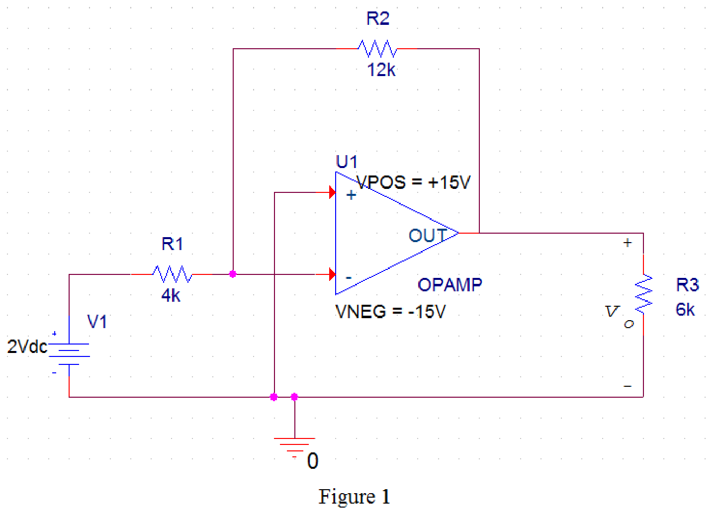
PSpice Simulation:
Draw the given circuit in PSPICE as shown in Figure 1.
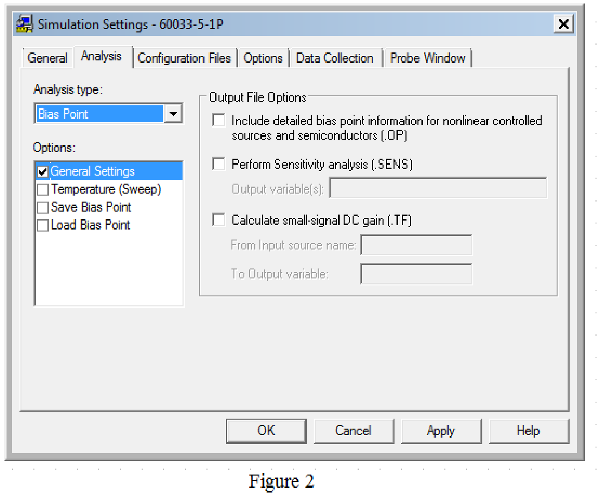
Provide the simulation settings as shown in Figure 2 to obtain output parameters.
After simulating the PSPICE circuit, the output voltage
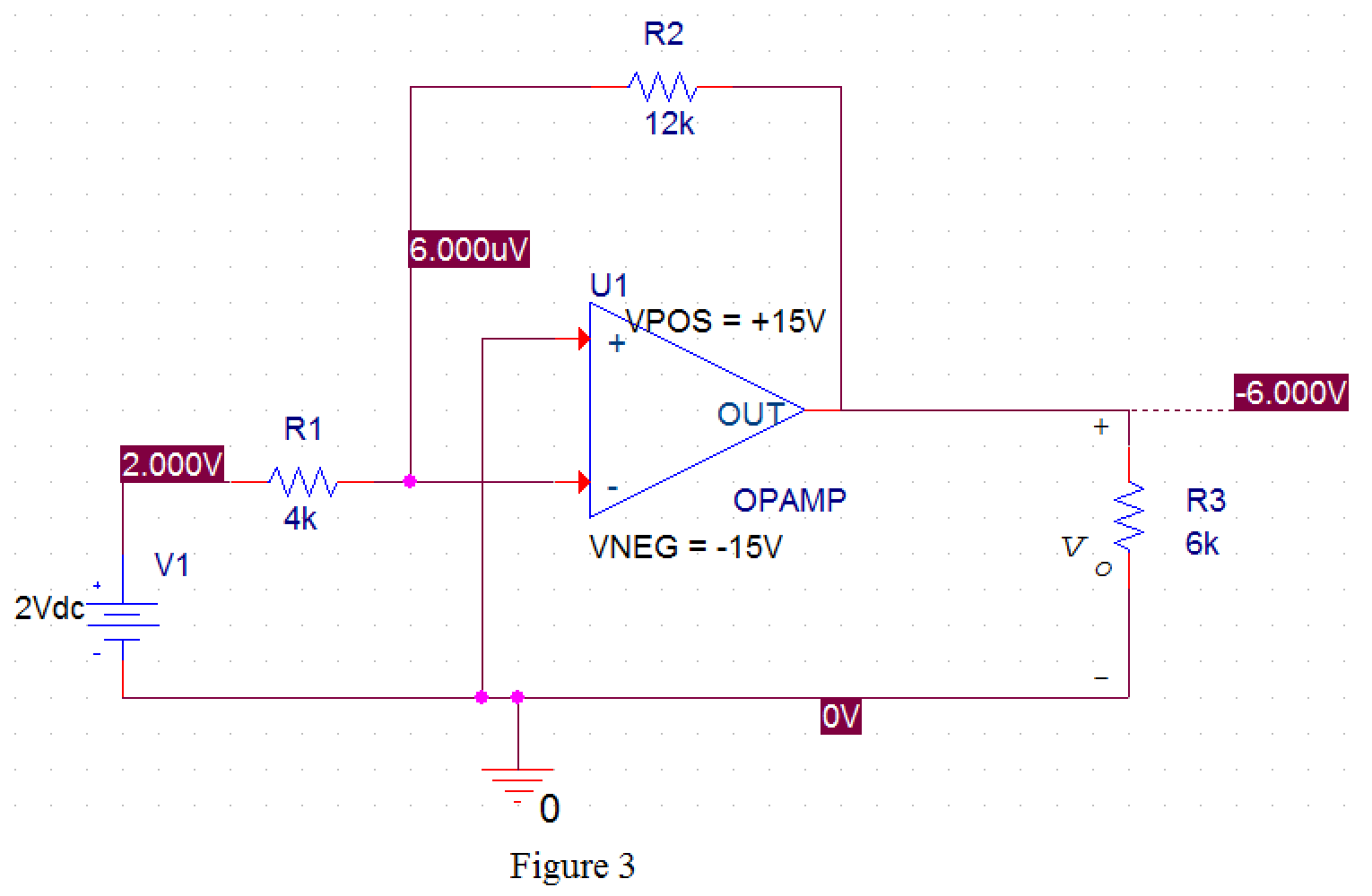
From Figure 3, the value of output voltage is
Conclusion:
Thus, the value of voltage
Want to see more full solutions like this?
Chapter 5 Solutions
EBK ELECTRIC CIRCUITS


- not use ai pleasearrow_forwardIn matlabarrow_forwardEXAMPLE 4.4 In a binary symmetric communication (BSC) channel, the input bits transmitted over the channel are either 0 or 1 with probabilities p and 1-p, respectively. Due to channel noise, errors are made. As shown in Figure 4.4, the channel is assumed to be symmetric, which means the probability of receiving 1 when 0 is transmitted is the same as the probability of receiving 0 when 1 is transmit- ted. The conditional probabilities of error are assumed to be each e. Determine the average prob- ability of error, also known as the bit error rate, as well as the a posteriori probabilities.arrow_forward
- What is the bandwidth requirement in Hz for baseband binary transmission at 64 kbps, if the roll-off factor is 0.25?arrow_forwardEXAMPLE 6.4 Suppose the roll-off factor is 25% and the bandwidth of a baseband transmission system satisfying the Nyquist criterion is 30 kHz. Determine the bit rate. Solution 1+α 1arrow_forwardEXAMPLE 4.9 In a communication system, the noise level is modeled as a Gaussian random variable with m=0 and ² = 0.0001. Determine P(X > 0.01) and P(-0.04 ≤x≤ 0.05). 3arrow_forward
- Suppose the random variable X is uniformly distributed between 0 and 1 with probability 0.25, takes on the value of 1 with probability p, and is uniformly distributed between 1 and 2 with probability 0.5. Determine p as well as the pdf and cdf of the random variable Xarrow_forwardconstants: A (medium) single phase transmission line 100 km long has the following Resistance/km = 0.25 2; Susceptance/km = 14 × 10 siemen; Reactance/km = 0.8 Receiving end line voltage = 66,000 V Assuming that the total capacitance of the line is localised at the receiving end alone, determine (i) the sending end current (ii) the sending end voltage (iii) regulation and (iv) supply power factor. The line is delivering 15,000 kW at 0.8 power factor lagging. Draw the phasor diagram to illustrate your calculations.arrow_forwardFor the power system given below, the voltage at bus 2 is kept at 1.03 pu. The maximum power can be delivered by G2 is 35 MW. Obtain the load flow solution. Take the base power 100 MVA. V₁ = 1.0520 G₁ 0.02+j0.06 G2 V2=1.03 P2 = 35 MW 0.08+j0.24 SL2 20+j50 MVA SL3 60+j25 MVA 0.06+j0.018arrow_forward
- General Directions: Read the questions carefully and answer (3*10=30marks) 1. Design a summing amplifier by choosing appropriate values of resistors an so that the output is 5 times the sum of the input voltages. (you are free to use any number of inputs, the type of op-amp, any value of resistors) 2. Derive the equation for the closed loop gain of the inverting and non-inverting Amplifier using appropriate circuit diagrams. 3. Determine the values read by the measuring devices using appropriate formulae www Voc +8V R₁ 33 k Rc 2.2 k ww WWW Poc 200 R₁₂ RE 10 kn 1.0 knarrow_forward十 : + B 日 العنوان I need a detailed drawing with explanation ややハメPV+96252 4 Project Homework: Create a simulation for a tank when the flowrate inside and outside the tank must range between 0 and 10 lit/s: 1) The level should be controlled within a range between more than zero to 1000 lit. 2) An alarm must be launched when the level is out of range (less than 100 and more than 900 lit). 3) When the capacity reaches to the maximum the motor turns OFF. area=A Qout -20 solve in lab view X9.01 *175*1arrow_forwardProject Homework: Create a simulation for a tank when the flowrate inside and outside the tank must range between 0 and 10 lit/s: 1) The level should be controlled within a range between more than zero to 1000 lit. 2) An alarm must be launched when the level is out of range (less than 100 and more than 900 lit). 3) When the capacity reaches to the maximum the motor turns OFF. Qin h C Qout area=A solve in lab viewarrow_forward
 Introductory Circuit Analysis (13th Edition)Electrical EngineeringISBN:9780133923605Author:Robert L. BoylestadPublisher:PEARSON
 Delmar's Standard Textbook Of ElectricityElectrical EngineeringISBN:9781337900348Author:Stephen L. HermanPublisher:Cengage Learning
 Programmable Logic ControllersElectrical EngineeringISBN:9780073373843Author:Frank D. PetruzellaPublisher:McGraw-Hill Education
 Fundamentals of Electric CircuitsElectrical EngineeringISBN:9780078028229Author:Charles K Alexander, Matthew SadikuPublisher:McGraw-Hill Education
 Electric Circuits. (11th Edition)Electrical EngineeringISBN:9780134746968Author:James W. Nilsson, Susan RiedelPublisher:PEARSON
 Engineering ElectromagneticsElectrical EngineeringISBN:9780078028151Author:Hayt, William H. (william Hart), Jr, BUCK, John A.Publisher:Mcgraw-hill Education,