
EBK MECHANICS OF MATERIALS
7th Edition
ISBN: 8220100257063
Author: BEER
Publisher: YUZU
expand_more
expand_more
format_list_bulleted
Concept explainers
Videos
Textbook Question
Chapter 5, Problem 159RP
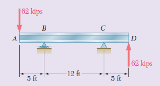
Knowing that the allowable normal stress for the steel used is 24 ksi, select the most economical wide-flange beam to support the loading shown.
Fig. P5.159
Expert Solution & Answer
Want to see the full answer?
Check out a sample textbook solution
Students have asked these similar questions
Answer all the calculations questions, if you are not not expert please don't attempt, don't use artificial intelligence
Please measure the size of the following object, and then
draw the front, top and side view in the AutoCAD
(including the printing)
just one arrow
for this one
30
Question 5
Calculate the Moment about the point B in
Nx m
B
500 N
A
2 m
1.2 m
0.8 m
300 N
7
Chapter 5 Solutions
EBK MECHANICS OF MATERIALS
Ch. 5.1 - 5.1 through 5.6 For the beam and loading shown,...Ch. 5.1 - 5.1 through 5.6 For the beam and loading shown,...Ch. 5.1 - 5.1 through 5.6 For the beam and loading shown,...Ch. 5.1 - 5.1 through 5.6 For the beam and loading shown,...Ch. 5.1 - 5.1 through 5.6 For the beam and loading shown,...Ch. 5.1 - 5.1 through 5.6 For the beam and loading shown,...Ch. 5.1 - 5.7 and 5.8 Draw the shear and bending-moment...Ch. 5.1 - 5.7 and 5.8 Draw the shear and bending-moment...Ch. 5.1 - 5.9 and 5.10 Draw the shear and bending-moment...Ch. 5.1 - 5.9 and 5.10 Draw the shear and bending-moment...
Ch. 5.1 - 5.11 and 5.12 Draw the shear and bending-moment...Ch. 5.1 - 5.11 and 5.12 Draw the shear and bending-moment...Ch. 5.1 - 5.13 and 5.14 Assuming that the reaction of the...Ch. 5.1 - 5.13 and 5.14 Assuming that the reaction of the...Ch. 5.1 - 5.15 and 5.16 For the beam and loading shown,...Ch. 5.1 - 5.15 and 5.16 For the beam and loading shown,...Ch. 5.1 - For the beam and loading shown, determine the...Ch. 5.1 - For the beam and loading shown, determine the...Ch. 5.1 - 5.19 and 5.20 For the beam and loading shown,...Ch. 5.1 - 5.19 and 5.20 For the beam and loading shown,...Ch. 5.1 - Draw the shear and bending-moment diagrams for the...Ch. 5.1 - 5.22 and 5.23 Draw the shear and bending-moment...Ch. 5.1 - 5.22 and 5.23 Draw the shear and bending-moment...Ch. 5.1 - 5.24 and 5.25 Draw the shear and bending-moment...Ch. 5.1 - 5.24 and 5.25 Draw the shear and bending-moment...Ch. 5.1 - Knowing that W = 12 kN, draw the shear and...Ch. 5.1 - Determine (a) the magnitude of the counterweight W...Ch. 5.1 - Determine (a) the distance a for which the...Ch. 5.1 - Knowing that P = Q = 480 N, determine (a) the...Ch. 5.1 - Solve Prob. 5.29, assuming that P = 480 N and Q =...Ch. 5.1 - Determine (a) the distance a for which the...Ch. 5.1 - A solid steel rod of diameter d is supported as...Ch. 5.1 - A solid steel bar has a square cross section of...Ch. 5.2 - Using the method of Sec. 5.2, solve Prob. 5.1a....Ch. 5.2 - Using the method of Sec. 5.2, solve Prob. 5.2a....Ch. 5.2 - Prob. 36PCh. 5.2 - Prob. 37PCh. 5.2 - Using the method of Sec. 5.2, solve Prob. 5.5a....Ch. 5.2 - Using the method of Sec. 5.2, solve Prob. 5.6a....Ch. 5.2 - Using the method of Sec. 5.2, solve Prob. 5.7. 5.7...Ch. 5.2 - Using the method of Sec. 5.2, solve Prob. 5.8. 5.7...Ch. 5.2 - Prob. 42PCh. 5.2 - Using the method of Sec. 5.2, solve Prob. 5.10....Ch. 5.2 - 5.44 and 5.45 Draw the shear and bending-moment...Ch. 5.2 - 5.44 and 5.45 Draw the shear and bending-moment...Ch. 5.2 - Prob. 46PCh. 5.2 - Prob. 47PCh. 5.2 - Prob. 48PCh. 5.2 - Using the method of Sec. 5.2, solve Prob. 5.20....Ch. 5.2 - 5.50 and 5.51 Determine (a) the equations of the...Ch. 5.2 - 5.50 and 5.51 Determine (a) the equations of the...Ch. 5.2 - 5.52 and 5.53 Determine (a) the equations of the...Ch. 5.2 - 5.52 and 5.53 Determine (a) the equations of the...Ch. 5.2 - 5.54 and 5.55 Draw the shear and bending-moment...Ch. 5.2 - 5.54 and 5.55 Draw the shear and bending-moment...Ch. 5.2 - 5.56 and 5.57 Draw the shear and bending-moment...Ch. 5.2 - 5.56 and 5.57 Draw the shear and bending-moment...Ch. 5.2 - 5.58 and 5.59 Draw the shear and bending-moment...Ch. 5.2 - 5.58 and 5.59 Draw the shear and bending-moment...Ch. 5.2 - Knowing that beam AB is in equilibrium under the...Ch. 5.2 - Knowing that beam AB is in equilibrium under the...Ch. 5.2 - The beam AB supports two concentrated loads P and...Ch. 5.2 - The beam AB supports a uniformly distributed load...Ch. 5.2 - Beam AB supports a uniformly distributed load of 2...Ch. 5.3 - 5.65 and 5.66 For the beam and loading shown,...Ch. 5.3 - 5.65 and 5.66 For the beam and loading shown,...Ch. 5.3 - 5.67 and 5.68 For the beam and loading shown,...Ch. 5.3 - 5.67 and 5.68 For the beam and loading shown,...Ch. 5.3 - 5.69 and 5.70 For the beam and loading shown,...Ch. 5.3 - 5.69 and 5.70 For the beam and loading shown,...Ch. 5.3 - 5.71 and 5.72 Knowing that the allowable normal...Ch. 5.3 - 5.71 and 5.72 Knowing that the allowable normal...Ch. 5.3 - 5.73 and 5.74 Knowing that the allowable normal...Ch. 5.3 - 5.73 and 5.74 Knowing that the allowable normal...Ch. 5.3 - 5.75 and 5.76 Knowing that the allowable normal...Ch. 5.3 - 5.75 and 5.76 Knowing that the allowable normal...Ch. 5.3 - 5.77 and 5.78 Knowing that the allowable normal...Ch. 5.3 - 5.77 and 5.78 Knowing that the allowable normal...Ch. 5.3 - A steel pipe of 100-mm diameter is to support the...Ch. 5.3 - Two metric rolled-steel channels are to be welded...Ch. 5.3 - Two rolled-steel channels are to be welded back to...Ch. 5.3 - Two L4 3 rolled-steel angles are bolted together...Ch. 5.3 - Assuming the upward reaction of the ground to be...Ch. 5.3 - Assuming the upward reaction of the ground to be...Ch. 5.3 - Determine the largest permissible distributed load...Ch. 5.3 - Solve Prob. 5.85, assuming that the cross section...Ch. 5.3 - Determine the largest permissible value of P for...Ch. 5.3 - Solve Prob. 5.87, assuming that the T-shaped beam...Ch. 5.3 - Beams AB, BC, and CD have the cross section shown...Ch. 5.3 - Beams AB, BC, and CD have the cross section shown...Ch. 5.3 - Each of the three rolled-steel beams shown...Ch. 5.3 - A 54-kip load is to be supported at the center of...Ch. 5.3 - A uniformly distributed load of 66 kN/m is to be...Ch. 5.3 - A roof structure consists of plywood and roofing...Ch. 5.3 - Solve Prob. 5.94, assuming that the 6-kN...Ch. 5.3 - Prob. 96PCh. 5.3 - Assuming that the front and rear axle loads remain...Ch. 5.4 - 5.98 through 5.100 (a) Using singularity...Ch. 5.4 - 5.98 through 5.100 (a) Using singularity...Ch. 5.4 - 5.98 through 5.100 (a) Using singularity...Ch. 5.4 - 5.101 through 5.103 (a) Using singularity...Ch. 5.4 - Prob. 102PCh. 5.4 - Prob. 103PCh. 5.4 - Prob. 104PCh. 5.4 - Prob. 105PCh. 5.4 - Prob. 106PCh. 5.4 - Prob. 107PCh. 5.4 - Prob. 108PCh. 5.4 - Prob. 109PCh. 5.4 - Prob. 110PCh. 5.4 - Prob. 111PCh. 5.4 - Prob. 112PCh. 5.4 - 5.112 and 5.113 (a) Using singularity functions,...Ch. 5.4 - Prob. 114PCh. 5.4 - 5.114 and 5.115 A beam is being designed to be...Ch. 5.4 - 5.116 and 5.117 A timber beam is being designed to...Ch. 5.4 - Prob. 117PCh. 5.4 - Prob. 118PCh. 5.4 - Prob. 119PCh. 5.4 - 5.118 through 5.121 Using a computer and step...Ch. 5.4 - Prob. 121PCh. 5.4 - 5.122 and 5.123 For the beam and loading shown and...Ch. 5.4 - 5.122 and 5.123 For the beam and loading shown and...Ch. 5.4 - 5.124 and 5.125 For the beam and loading shown and...Ch. 5.4 - Prob. 125PCh. 5.5 - 5.126 and 5.127 The beam AB, consisting of a...Ch. 5.5 - Prob. 127PCh. 5.5 - 5.128 and 5.129 The beam AB, consisting of a...Ch. 5.5 - 5.128 and 5.129 The beam AB, consisting of a...Ch. 5.5 - Prob. 130PCh. 5.5 - Prob. 131PCh. 5.5 - Prob. 132PCh. 5.5 - 5.132 and 5.133 A preliminary design on the use of...Ch. 5.5 - Prob. 134PCh. 5.5 - Prob. 135PCh. 5.5 - Prob. 136PCh. 5.5 - Prob. 137PCh. 5.5 - Prob. 138PCh. 5.5 - Prob. 139PCh. 5.5 - Assuming that the length and width of the cover...Ch. 5.5 - Two cover plates, each 12 in. thick, are welded to...Ch. 5.5 - Two cover plates, each 12 in. thick, are welded to...Ch. 5.5 - Prob. 143PCh. 5.5 - Prob. 144PCh. 5.5 - Two cover plates, each 7.5 mm thick, are welded to...Ch. 5.5 - Prob. 146PCh. 5.5 - Prob. 147PCh. 5.5 - For the tapered beam shown, determine (a) the...Ch. 5.5 - Prob. 149PCh. 5.5 - Prob. 150PCh. 5.5 - Prob. 151PCh. 5 - Draw the shear and bending-moment diagrams for the...Ch. 5 - Draw the shear and bending-moment diagrams for the...Ch. 5 - Determine (a) the distance a for which the...Ch. 5 - For the beam and loading shown, determine the...Ch. 5 - Draw the shear and bending-moment diagrams for the...Ch. 5 - Beam AB, of length L and square cross section of...Ch. 5 - Prob. 158RPCh. 5 - Knowing that the allowable normal stress for the...Ch. 5 - Prob. 160RPCh. 5 - (a) Using singularity functions, find the...Ch. 5 - Prob. 162RPCh. 5 - Prob. 163RP
Knowledge Booster


Learn more about
Need a deep-dive on the concept behind this application? Look no further. Learn more about this topic, mechanical-engineering and related others by exploring similar questions and additional content below.Similar questions
- Given that an L-shaped member (OAB) can rotate about OA, determine the moment vector created by the force about the line OA at the instant shown in the figure below. OA lies in the xy-plane, and the AB part is vertical. Express your answer as a Cartesian vector.arrow_forwardDetermine the magnitude of the moment created by the force about the point A.arrow_forward= MMB 241- Tutorial 1.pdf 2/3 80% + + 10. Determine a ats = 1 m v (m/s) 4 s (m) 2 11. Draw the v-t and s-t graphs if v = 0, s=0 when t=0. a (m/s²) 2 t(s) 12. Draw the v-t graph if v = 0 when t=0. Find the equation v = f(t) for each a (m/s²) 2 segment. 2 -2 13. Determine s and a when t = 3 s if s=0 when t = 0. v (m/s) 2 t(s) t(s) 2arrow_forward
- Q.5) A cylinder is supported by spring AD and cables AB and AC as shown. The spring has an at rest length (unstretched length) of 4 meters. If the maximum allowable tension in cables AB and AC is 200 N, determine (a) the largest mass (kg) of cylinder E the system can support, (b) the necessary spring constant (stiffness) to maintain equilibrium, and (b) the tension (magnitude) in each cable when supporting the maximum load found in part (a). B 4 m 3 m A E 1 m 3 m D 5 marrow_forwardDetermine the moment created by the force about the point O. Express your answer as a Cartesian vector.arrow_forward4. An impeller rotating at 1150 rpm has the following data: b, = 1 ¼ in., b2 = ¾ in., d, = 7 in., d2 = 15 in., B1 = 18", B2 = 20°, cross-sectional area A = Db if vane thickness is neglected. Assuming radial inlet flow, determine the theoretical capacity in gpm head in ft horsepower 5. If the impeller in Problem (4) develops an actual head of 82 ft and delivers 850 gpm at the point of maximum efficiency and requires 22 BHP. Determine overall pump efficiency virtual velocities V2 and W2arrow_forward
- (30 pts) Problem 1 A thin uniform rod of mass m and length 2r rests in a smooth hemispherical bowl of radius r. A moment M mgr 4 is applied to the rod. Assume that the bowl is fixed and its rim is in the horizontal plane. HINT: It will help you to find the length l of that portion of the rod that remains outside the bowl. M 2r a) How many degrees of freedom does this system have? b) Write an equation for the virtual work in terms of the angle 0 and the motion of the center of mass (TF) c) Derive an equation for the variation in the position of the center of mass (i.e., Sŕƒ) a. HINT: Use the center of the bowl as the coordinate system origin for the problem. d) In the case of no applied moment (i.e., M 0), derive an equation that can be used to solve for the equilibrium angle of the rod. DO NOT solve the equation e) In the case of an applied moment (i.e., M = mgr = -) derive an equation that can be used to 4 solve for the equilibrium angle of the rod. DO NOT solve the equation. f) Can…arrow_forwardPlease show all work step by steparrow_forwardCopyright 2013 Pearson Education, publishing as Prentice Hall 2. Determine the force that the jaws J of the metal cutters exert on the smooth cable C if 100-N forces are applied to the handles. The jaws are pinned at E and A, and D and B. There is also a pin at F. E 400 mm 15° D B 30 mm² 80 mm/ 20 mm 15° $15° 20 mm 400 mm 15° 100 N 100 N 15°arrow_forward
arrow_back_ios
SEE MORE QUESTIONS
arrow_forward_ios
Recommended textbooks for you
 Elements Of ElectromagneticsMechanical EngineeringISBN:9780190698614Author:Sadiku, Matthew N. O.Publisher:Oxford University Press
 Mechanics of Materials (10th Edition)Mechanical EngineeringISBN:9780134319650Author:Russell C. HibbelerPublisher:PEARSON
 Thermodynamics: An Engineering ApproachMechanical EngineeringISBN:9781259822674Author:Yunus A. Cengel Dr., Michael A. BolesPublisher:McGraw-Hill Education
 Control Systems EngineeringMechanical EngineeringISBN:9781118170519Author:Norman S. NisePublisher:WILEY
 Mechanics of Materials (MindTap Course List)Mechanical EngineeringISBN:9781337093347Author:Barry J. Goodno, James M. GerePublisher:Cengage Learning
 Engineering Mechanics: StaticsMechanical EngineeringISBN:9781118807330Author:James L. Meriam, L. G. Kraige, J. N. BoltonPublisher:WILEY
Elements Of Electromagnetics
Mechanical Engineering
ISBN:9780190698614
Author:Sadiku, Matthew N. O.
Publisher:Oxford University Press
Mechanics of Materials (10th Edition)
Mechanical Engineering
ISBN:9780134319650
Author:Russell C. Hibbeler
Publisher:PEARSON
Thermodynamics: An Engineering Approach
Mechanical Engineering
ISBN:9781259822674
Author:Yunus A. Cengel Dr., Michael A. Boles
Publisher:McGraw-Hill Education
Control Systems Engineering
Mechanical Engineering
ISBN:9781118170519
Author:Norman S. Nise
Publisher:WILEY
Mechanics of Materials (MindTap Course List)
Mechanical Engineering
ISBN:9781337093347
Author:Barry J. Goodno, James M. Gere
Publisher:Cengage Learning
Engineering Mechanics: Statics
Mechanical Engineering
ISBN:9781118807330
Author:James L. Meriam, L. G. Kraige, J. N. Bolton
Publisher:WILEY
Everything About COMBINED LOADING in 10 Minutes! Mechanics of Materials; Author: Less Boring Lectures;https://www.youtube.com/watch?v=N-PlI900hSg;License: Standard youtube license