
Basic Engineering Circuit Analysis
11th Edition
ISBN: 9781118992661
Author: Irwin, J. David, NELMS, R. M., 1939-
Publisher: Wiley,
expand_more
expand_more
format_list_bulleted
Concept explainers
Videos
Textbook Question
thumb_up100%
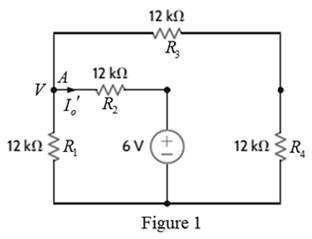
Chapter 5, Problem 11P
Find
Expert Solution & Answer
Want to see the full answer?
Check out a sample textbook solution
Students have asked these similar questions
Find the Z-transform including the region of convergence for the following function
12
(¹)" [u(n) – u(n − 5)]
-
Find the inverse Z-traform of X(z)=
z 2 +z
(z-0.125)³ (z-0.25)
A separately excited 6-kilowatt generator has a terminal voltage of 135V at no load. At full load, the terminal voltage is 120V with speed and field excitation unchanged. Armature resistance = = 0.25 ohm.
A. What is the amount of voltage decrease caused by armature reaction and the voltage regulation?
Chapter 5 Solutions
Basic Engineering Circuit Analysis
Ch. 5 - Find Io in the network in Fig. P5.1 using...Ch. 5 - Find Io in the network in Fig. P5.2 using...Ch. 5 - Find Io in the network in Fig. P5.3 using...Ch. 5 - Find Vo in the network in Fig. P5.4 using...Ch. 5 - Find Io in the circuit in Fig. P5.5 using...Ch. 5 - Find Io in the network in Fig. P5.6 using...Ch. 5 - Find Io in the circuit in Fig. P5.7 using...Ch. 5 - Find Vo in the network in Fig. P5.8 using...Ch. 5 - Find Vo in the network in Fig. P5.9 using...Ch. 5 - In the network in Fig. P5.l0, find using...
Ch. 5 - Find Io in the network in Fig. P5.11 using...Ch. 5 - Find Io in the network in Fig. P5.12 using...Ch. 5 - Find IA in the network in Fig. P5.13 using...Ch. 5 - Using superposition, find IA in the circuit in...Ch. 5 - Find IA in the network in Fig. P5.15 using...Ch. 5 - Using superposition, find Vo in the network in...Ch. 5 - Use superposition to find Io in the circuit in...Ch. 5 - Use superposition to find Io in the network in...Ch. 5 - Use superposition to find Vo in the circuit in...Ch. 5 - Find Vo in the circuit in Fig. P5.20 using...Ch. 5 - Find Io in the circuit in Fig. P5.21 using...Ch. 5 - Use superposition to find Io in the circuit in...Ch. 5 - Use superposition to find Io in the network in...Ch. 5 - Use superposition to find Io in the circuit in...Ch. 5 - Use Thévenins theorem to find Vo in the network...Ch. 5 - Use Thévenins theorem to find in the network in...Ch. 5 - Use Thévenins theorem to find Vo in the network...Ch. 5 - Find Io in the network in Fig. P5.28 using...Ch. 5 - Find Vo in the network in Fig. P5.28 using...Ch. 5 - Use Thévenins theorem to find 10 in the network...Ch. 5 - Find Vo in the network in Fig. P5.31 using...Ch. 5 - Find Io in the circuit in Fig. P5.32 using...Ch. 5 - Find Io in the network in Fig. P5.33 using...Ch. 5 - Find Io in the network in Fig. P5.34 using...Ch. 5 - Find Io in the circuit in Fig. P5.35 using...Ch. 5 - Find Io in the network in Fig. P5.36 using...Ch. 5 - Using Thévenins theorem, find IA in the circuit...Ch. 5 - Find Vo in the network in Fig. P5.38 using...Ch. 5 - Find Vo in the circuit in Fig. P5.39 using...Ch. 5 - Find Io in the circuit in Fig. P5.40 using...Ch. 5 - Find Vo in the network in Fig. P5.41 using...Ch. 5 - Find Io in the network in Fig. P5.42 using...Ch. 5 - Find Vo in Fig. P5.43 using Thévenins theorem.Ch. 5 - Use Thévenins theorem to find Vo in the circuit...Ch. 5 - Use Thévenins theorem to find Io in Fig. P5.45.Ch. 5 - Find Vo in the network in Fig. P5.46 using...Ch. 5 - Use Thévenins theorem to find Io in the network...Ch. 5 - Use Thévenins theorem to find Io in the circuit...Ch. 5 - Given the linear circuit in Fig. P5.49, it is...Ch. 5 - If an 8-k load is connected to the terminals of...Ch. 5 - Use Nortons theorem to find Io in the circuit in...Ch. 5 - Find Io in the network in Fig. P5.52 using Nortons...Ch. 5 - Use Nortons theorem to find Io in the circuit in...Ch. 5 - Use Nortons theorem to find Vo in the network in...Ch. 5 - Find Io in the network in Fig. P5.55 using Nortons...Ch. 5 - Use Nortons theorem to find Vo in the network in...Ch. 5 - Find Vo in the network in Fig. P5.57 using Nortons...Ch. 5 - Use Nortons theorem to find Io in the circuit in...Ch. 5 - Find Vo in the circuit in Fig. P5.59 using Nortons...Ch. 5 - Use Nortons theorem to find Io in the network in...Ch. 5 - Use Nortons theorem to find Io in the circuit in...Ch. 5 - In the network in Fig. P5.62, find Vo using...Ch. 5 - Use Thévenins theorem to find 10 in the circuit...Ch. 5 - Find Vo in the network in Fig. P5.64 using...Ch. 5 - Use Thévenins theorem to find Vo in the circuit...Ch. 5 - Find Io in the circuit in Fig. P5.66 using...Ch. 5 - Use Thévenins theorem to find Io in the circuit...Ch. 5 - Use Thévenins theorem to find Vo in the circuit...Ch. 5 - Find Vo in the network in Fig. P5.69 using...Ch. 5 - Use Nortons theorem to find Vo in the network in...Ch. 5 - Find Vo in the circuit in Fig. P5.71 using...Ch. 5 - Find Vo in the network in Fig. P5.72 using...Ch. 5 - Find Vo in the network in Fig. P5.73 using Nortons...Ch. 5 - Use Thévenins theorem to find the power supplied...Ch. 5 - Find Vo in the circuit in Fig. P5.75 using...Ch. 5 - Find Vo in the network in Fig. P5.76 using...Ch. 5 - Find Vo in the network in Fig. P5.77 using...Ch. 5 - Use Thévenins theorem to find I2 in the circuit...Ch. 5 - Use Thévenins theorem to find Vo in the circuit...Ch. 5 - Use Thévenins theorem to find Vo in the circuit...Ch. 5 - Use Thévenins theorem to find Io in the network...Ch. 5 - Use Thévenins theorem to find Vo in the network...Ch. 5 - Find the Thévenin equivalent of the network in...Ch. 5 - Find the Thévenin equivalent of the network in...Ch. 5 - Find the Thévenin equivalent of the circuit in...Ch. 5 - Find the Thévenin equivalent of the network in...Ch. 5 - Find the Thévenin equivalent circuit of the...Ch. 5 - Find Vo in the network in Fig. P5.88 using source...Ch. 5 - Find Io in the network in Fig. P5.89 using source...Ch. 5 - Use source transformation to find Vo in the...Ch. 5 - Find 10 in the network in Fig. P5.91 using source...Ch. 5 - Find Vo in the network in Fig. P5.92 using source...Ch. 5 - Use source transformation to find Io in the...Ch. 5 - Find the Thévenin equivalent circuit of the...Ch. 5 - Find Io in the circuit in Fig. P5.95 using source...Ch. 5 - Find Io in the network in Fig. P5.96 using source...Ch. 5 - Find Io in the network in Fig. P5.97 using source...Ch. 5 - Find Vo in the network in Fig. P5.98 using source...Ch. 5 - Find Io in the network in Fig. P5.99 using source...Ch. 5 - Find in the circuit in Fig. P5.100 using source...Ch. 5 - Use source transformation to find Io in the...Ch. 5 - Using source transformation, find Vo in the...Ch. 5 - Use source transformation to find Io in the...Ch. 5 - Use source transformation to find Io in the...Ch. 5 - Use source transformation to find 10 in the...Ch. 5 - Using source transformation, find 10 in the...Ch. 5 - Use source exchange to find Io in the network in...Ch. 5 - Use a combination of Y- transformation and source...Ch. 5 - Use source exchange to find Io in the circuit in...Ch. 5 - Use source exchange to find Io in the network in...Ch. 5 - Use source exchange to find Io in the network in...Ch. 5 - Find RL in the network in Fig. P5.112 in order to...Ch. 5 - In the network in Fig. P5.113, find RL for maximum...Ch. 5 - Find RL for maximum power transfer and the maximum...Ch. 5 - Find RL for maximum power transfer and the maximum...Ch. 5 - Find RL for maximum power transfer and the maximum...Ch. 5 - Find RL for maximum power transfer and the maximum...Ch. 5 - Determine the value of RL in the network in Fig....Ch. 5 - Find RL for maximum power transfer and the maximum...Ch. 5 - Find the value of RL in the network in Fig. P5.120...Ch. 5 - Find the value of RL for maximum power transfer...Ch. 5 - Find the maximum power that can be transferred to...Ch. 5 - In the network in Fig. P5.123, find the value of...Ch. 5 - In the network in Fig. P5.124, find the value of...Ch. 5 - Find the value of RL in Fig. P5.125 for maximum...Ch. 5 - Calculate the maximum power that can be...Ch. 5 - Find RL for maximum power transfer and the maximum...Ch. 5 - Find the value of RL in Fig. P5.128 for maximum...Ch. 5 - A cell phone antenna picks up a call. If the...Ch. 5 - Some young engineers at the local electrical...Ch. 5 - Determine the maximum power that can be delivered...Ch. 5 - Find the value of the load RL in the network in...Ch. 5 - Find the value of RL in the network in fig. 5PFE-3...Ch. 5 - What is the current I in Fig. 5PFE4? a. 8 Ac. 0 A...Ch. 5 - What is the open-circuit voltage Voc at terminals...
Additional Engineering Textbook Solutions
Find more solutions based on key concepts
Explain what is meant by the term conditionally executed.
Starting Out with Python (4th Edition)
List the specific functions of a DBMS.
Database Concepts (8th Edition)
Assume x is an int variable, and rand references a Random object. What does the following statement do? x = ran...
Starting Out with Java: From Control Structures through Objects (7th Edition) (What's New in Computer Science)
The switch shown in Fig. P 7.4 has been open for a long time before closing at t = 0.
Figure P7.4
Find io(0−),...
Electric Circuits. (11th Edition)
Display 7.10 shows a function called search, which searches an array for a specified integer. Give a function t...
Problem Solving with C++ (10th Edition)
102* The sum of seven interior angles ofa closed-polygon traverse each read to the nearest
3 ” is
$99 a 59 '39...
Elementary Surveying: An Introduction To Geomatics (15th Edition)
Knowledge Booster


Learn more about
Need a deep-dive on the concept behind this application? Look no further. Learn more about this topic, electrical-engineering and related others by exploring similar questions and additional content below.Similar questions
- J. A sampling system can be set to adjust its sampling rate in 25 He steps. Considering the signal spectra pleted below, specify the minimum sampling rate setting for the signals: a)x(1) b)(1)+(1) 985)+20 0,09 0:00 0,0 106) 100) SORO -2501 250V (1500+501) 。 1500+50V 201 2500arrow_forward1. For this problem, state your answers to 4 significant figures. (1)For the message signal shown below, sketch the phase-meduced form and 4-5/N rad V. Specify values of the miniman & maximum instantaneous frequencies in He (b) Find the approximate bandwidth of the phase-modulaud signal, assuming that the effective handwidth of the message is equal to its 4th harmonic frequency (N-2015 101 2x10' 159-arrow_forward4. For the filter shown below, with an input signal whose PSD by 20 (4) Find the pet power in (b) Find the trafor (4) Find the power spel de PSD) of 4 put signat (d) Find the talutput power of the signal a C-58-18 -arrow_forward
- 2.80+4'selevision stations are to be transmited deough a single fiber optic cable using uncompressed PCM and TDM. Each station comprises one 22 kHz audio channel samplod at (1+0.24) times the Nyquist rate and encoded at a bit dop of 12 bSa, plan one 2.0 MHz video channel sampled at the mininum rite The video signal must be transmitted with an accuracy of better than (20 3) Find De (minimum) bit depth of the video signal. b) Find the bit rate associated with a single television station, including both audio and video e) Find the minimus bandwidth (the total multiplexed PCM signal.arrow_forward5. Consider a Shor who (4) Skh the impulse repom of the Chor for -5%, a-2+5. Omie weer de Sher is drain canal and explain sty odical, chronic sale of a hat will result in a coal for, and expls why itarrow_forwardFind the inverse Z-transform of X(z) using partial fraction method X(z) = z²+Z Z2-3Z+2 for i) ROC 12 iii) ROC |z| <1arrow_forward
- .The previous solution does not explain the steps Consider the signal: f(t) = 글씨를 1 0, otherwise Use the Fourier transform formula to find F(w).arrow_forward3. Find the transfer function and show all steps.arrow_forward8. Determine the center frequency and Bandwidth of the following bandpass filter, show all steps.arrow_forward
arrow_back_ios
SEE MORE QUESTIONS
arrow_forward_ios
Recommended textbooks for you
 Introductory Circuit Analysis (13th Edition)Electrical EngineeringISBN:9780133923605Author:Robert L. BoylestadPublisher:PEARSON
 Delmar's Standard Textbook Of ElectricityElectrical EngineeringISBN:9781337900348Author:Stephen L. HermanPublisher:Cengage Learning
 Programmable Logic ControllersElectrical EngineeringISBN:9780073373843Author:Frank D. PetruzellaPublisher:McGraw-Hill Education
 Fundamentals of Electric CircuitsElectrical EngineeringISBN:9780078028229Author:Charles K Alexander, Matthew SadikuPublisher:McGraw-Hill Education
 Electric Circuits. (11th Edition)Electrical EngineeringISBN:9780134746968Author:James W. Nilsson, Susan RiedelPublisher:PEARSON
 Engineering ElectromagneticsElectrical EngineeringISBN:9780078028151Author:Hayt, William H. (william Hart), Jr, BUCK, John A.Publisher:Mcgraw-hill Education,
Introductory Circuit Analysis (13th Edition)
Electrical Engineering
ISBN:9780133923605
Author:Robert L. Boylestad
Publisher:PEARSON
Delmar's Standard Textbook Of Electricity
Electrical Engineering
ISBN:9781337900348
Author:Stephen L. Herman
Publisher:Cengage Learning
Programmable Logic Controllers
Electrical Engineering
ISBN:9780073373843
Author:Frank D. Petruzella
Publisher:McGraw-Hill Education
Fundamentals of Electric Circuits
Electrical Engineering
ISBN:9780078028229
Author:Charles K Alexander, Matthew Sadiku
Publisher:McGraw-Hill Education
Electric Circuits. (11th Edition)
Electrical Engineering
ISBN:9780134746968
Author:James W. Nilsson, Susan Riedel
Publisher:PEARSON
Engineering Electromagnetics
Electrical Engineering
ISBN:9780078028151
Author:Hayt, William H. (william Hart), Jr, BUCK, John A.
Publisher:Mcgraw-hill Education,
Current Divider Rule; Author: Neso Academy;https://www.youtube.com/watch?v=hRU1mKWUehY;License: Standard YouTube License, CC-BY