
Basic Engineering Circuit Analysis
11th Edition
ISBN: 9781118992661
Author: Irwin, J. David, NELMS, R. M., 1939-
Publisher: Wiley,
expand_more
expand_more
format_list_bulleted
Concept explainers
Videos
Textbook Question
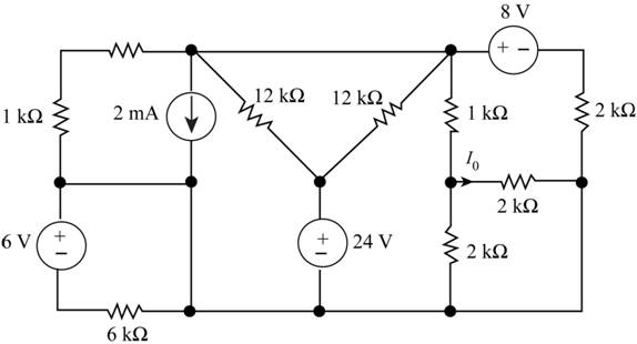
Chapter 5, Problem 109P
Use source exchange to find
Expert Solution & Answer
Want to see the full answer?
Check out a sample textbook solution
Students have asked these similar questions
Please draw logic circuit
A 220-volt, 20-horsepower compound motor (long shunt, Figure 21–16A) has an armature resistance of 0.25 ohm, series field resistance of 0.19 ohm, and shunt field resistance of 33 ohms.
a. Calculate the current taken by the motor at the instant of starting if it is con-nected directly to the 220-volt line.
b. Calculate the current when the motor is running if the armature is developing 184 volts counter-emf.
Design a modulo-11 ripple (asynchronous) up-counter with negative edge-triggered T flip-flops and draw the corresponding logic circuit.
(I)Build the state diagram and extract the state table
(II)Draw the logic circuit
(III)What is the maximum modulus of the counter?
Chapter 5 Solutions
Basic Engineering Circuit Analysis
Ch. 5 - Find Io in the network in Fig. P5.1 using...Ch. 5 - Find Io in the network in Fig. P5.2 using...Ch. 5 - Find Io in the network in Fig. P5.3 using...Ch. 5 - Find Vo in the network in Fig. P5.4 using...Ch. 5 - Find Io in the circuit in Fig. P5.5 using...Ch. 5 - Find Io in the network in Fig. P5.6 using...Ch. 5 - Find Io in the circuit in Fig. P5.7 using...Ch. 5 - Find Vo in the network in Fig. P5.8 using...Ch. 5 - Find Vo in the network in Fig. P5.9 using...Ch. 5 - In the network in Fig. P5.l0, find using...
Ch. 5 - Find Io in the network in Fig. P5.11 using...Ch. 5 - Find Io in the network in Fig. P5.12 using...Ch. 5 - Find IA in the network in Fig. P5.13 using...Ch. 5 - Using superposition, find IA in the circuit in...Ch. 5 - Find IA in the network in Fig. P5.15 using...Ch. 5 - Using superposition, find Vo in the network in...Ch. 5 - Use superposition to find Io in the circuit in...Ch. 5 - Use superposition to find Io in the network in...Ch. 5 - Use superposition to find Vo in the circuit in...Ch. 5 - Find Vo in the circuit in Fig. P5.20 using...Ch. 5 - Find Io in the circuit in Fig. P5.21 using...Ch. 5 - Use superposition to find Io in the circuit in...Ch. 5 - Use superposition to find Io in the network in...Ch. 5 - Use superposition to find Io in the circuit in...Ch. 5 - Use Thévenins theorem to find Vo in the network...Ch. 5 - Use Thévenins theorem to find in the network in...Ch. 5 - Use Thévenins theorem to find Vo in the network...Ch. 5 - Find Io in the network in Fig. P5.28 using...Ch. 5 - Find Vo in the network in Fig. P5.28 using...Ch. 5 - Use Thévenins theorem to find 10 in the network...Ch. 5 - Find Vo in the network in Fig. P5.31 using...Ch. 5 - Find Io in the circuit in Fig. P5.32 using...Ch. 5 - Find Io in the network in Fig. P5.33 using...Ch. 5 - Find Io in the network in Fig. P5.34 using...Ch. 5 - Find Io in the circuit in Fig. P5.35 using...Ch. 5 - Find Io in the network in Fig. P5.36 using...Ch. 5 - Using Thévenins theorem, find IA in the circuit...Ch. 5 - Find Vo in the network in Fig. P5.38 using...Ch. 5 - Find Vo in the circuit in Fig. P5.39 using...Ch. 5 - Find Io in the circuit in Fig. P5.40 using...Ch. 5 - Find Vo in the network in Fig. P5.41 using...Ch. 5 - Find Io in the network in Fig. P5.42 using...Ch. 5 - Find Vo in Fig. P5.43 using Thévenins theorem.Ch. 5 - Use Thévenins theorem to find Vo in the circuit...Ch. 5 - Use Thévenins theorem to find Io in Fig. P5.45.Ch. 5 - Find Vo in the network in Fig. P5.46 using...Ch. 5 - Use Thévenins theorem to find Io in the network...Ch. 5 - Use Thévenins theorem to find Io in the circuit...Ch. 5 - Given the linear circuit in Fig. P5.49, it is...Ch. 5 - If an 8-k load is connected to the terminals of...Ch. 5 - Use Nortons theorem to find Io in the circuit in...Ch. 5 - Find Io in the network in Fig. P5.52 using Nortons...Ch. 5 - Use Nortons theorem to find Io in the circuit in...Ch. 5 - Use Nortons theorem to find Vo in the network in...Ch. 5 - Find Io in the network in Fig. P5.55 using Nortons...Ch. 5 - Use Nortons theorem to find Vo in the network in...Ch. 5 - Find Vo in the network in Fig. P5.57 using Nortons...Ch. 5 - Use Nortons theorem to find Io in the circuit in...Ch. 5 - Find Vo in the circuit in Fig. P5.59 using Nortons...Ch. 5 - Use Nortons theorem to find Io in the network in...Ch. 5 - Use Nortons theorem to find Io in the circuit in...Ch. 5 - In the network in Fig. P5.62, find Vo using...Ch. 5 - Use Thévenins theorem to find 10 in the circuit...Ch. 5 - Find Vo in the network in Fig. P5.64 using...Ch. 5 - Use Thévenins theorem to find Vo in the circuit...Ch. 5 - Find Io in the circuit in Fig. P5.66 using...Ch. 5 - Use Thévenins theorem to find Io in the circuit...Ch. 5 - Use Thévenins theorem to find Vo in the circuit...Ch. 5 - Find Vo in the network in Fig. P5.69 using...Ch. 5 - Use Nortons theorem to find Vo in the network in...Ch. 5 - Find Vo in the circuit in Fig. P5.71 using...Ch. 5 - Find Vo in the network in Fig. P5.72 using...Ch. 5 - Find Vo in the network in Fig. P5.73 using Nortons...Ch. 5 - Use Thévenins theorem to find the power supplied...Ch. 5 - Find Vo in the circuit in Fig. P5.75 using...Ch. 5 - Find Vo in the network in Fig. P5.76 using...Ch. 5 - Find Vo in the network in Fig. P5.77 using...Ch. 5 - Use Thévenins theorem to find I2 in the circuit...Ch. 5 - Use Thévenins theorem to find Vo in the circuit...Ch. 5 - Use Thévenins theorem to find Vo in the circuit...Ch. 5 - Use Thévenins theorem to find Io in the network...Ch. 5 - Use Thévenins theorem to find Vo in the network...Ch. 5 - Find the Thévenin equivalent of the network in...Ch. 5 - Find the Thévenin equivalent of the network in...Ch. 5 - Find the Thévenin equivalent of the circuit in...Ch. 5 - Find the Thévenin equivalent of the network in...Ch. 5 - Find the Thévenin equivalent circuit of the...Ch. 5 - Find Vo in the network in Fig. P5.88 using source...Ch. 5 - Find Io in the network in Fig. P5.89 using source...Ch. 5 - Use source transformation to find Vo in the...Ch. 5 - Find 10 in the network in Fig. P5.91 using source...Ch. 5 - Find Vo in the network in Fig. P5.92 using source...Ch. 5 - Use source transformation to find Io in the...Ch. 5 - Find the Thévenin equivalent circuit of the...Ch. 5 - Find Io in the circuit in Fig. P5.95 using source...Ch. 5 - Find Io in the network in Fig. P5.96 using source...Ch. 5 - Find Io in the network in Fig. P5.97 using source...Ch. 5 - Find Vo in the network in Fig. P5.98 using source...Ch. 5 - Find Io in the network in Fig. P5.99 using source...Ch. 5 - Find in the circuit in Fig. P5.100 using source...Ch. 5 - Use source transformation to find Io in the...Ch. 5 - Using source transformation, find Vo in the...Ch. 5 - Use source transformation to find Io in the...Ch. 5 - Use source transformation to find Io in the...Ch. 5 - Use source transformation to find 10 in the...Ch. 5 - Using source transformation, find 10 in the...Ch. 5 - Use source exchange to find Io in the network in...Ch. 5 - Use a combination of Y- transformation and source...Ch. 5 - Use source exchange to find Io in the circuit in...Ch. 5 - Use source exchange to find Io in the network in...Ch. 5 - Use source exchange to find Io in the network in...Ch. 5 - Find RL in the network in Fig. P5.112 in order to...Ch. 5 - In the network in Fig. P5.113, find RL for maximum...Ch. 5 - Find RL for maximum power transfer and the maximum...Ch. 5 - Find RL for maximum power transfer and the maximum...Ch. 5 - Find RL for maximum power transfer and the maximum...Ch. 5 - Find RL for maximum power transfer and the maximum...Ch. 5 - Determine the value of RL in the network in Fig....Ch. 5 - Find RL for maximum power transfer and the maximum...Ch. 5 - Find the value of RL in the network in Fig. P5.120...Ch. 5 - Find the value of RL for maximum power transfer...Ch. 5 - Find the maximum power that can be transferred to...Ch. 5 - In the network in Fig. P5.123, find the value of...Ch. 5 - In the network in Fig. P5.124, find the value of...Ch. 5 - Find the value of RL in Fig. P5.125 for maximum...Ch. 5 - Calculate the maximum power that can be...Ch. 5 - Find RL for maximum power transfer and the maximum...Ch. 5 - Find the value of RL in Fig. P5.128 for maximum...Ch. 5 - A cell phone antenna picks up a call. If the...Ch. 5 - Some young engineers at the local electrical...Ch. 5 - Determine the maximum power that can be delivered...Ch. 5 - Find the value of the load RL in the network in...Ch. 5 - Find the value of RL in the network in fig. 5PFE-3...Ch. 5 - What is the current I in Fig. 5PFE4? a. 8 Ac. 0 A...Ch. 5 - What is the open-circuit voltage Voc at terminals...
Additional Engineering Textbook Solutions
Find more solutions based on key concepts
The while loop is a pretest loop.
Starting Out with Python (4th Edition)
float ratings[] ;
Starting Out with C++ from Control Structures to Objects (9th Edition)
Define a method called changePopulation that could be added to the definition of the class SpeciesSecondTry in ...
Java: An Introduction to Problem Solving and Programming (8th Edition)
State whether each of the following is true or false. If false, explain why. Java considers the variables numbe...
Java How to Program, Early Objects (11th Edition) (Deitel: How to Program)
Write code that displays the contents of the int variable i in binary, hexadecimal, and octal.
Starting Out with Java: From Control Structures through Objects (7th Edition) (What's New in Computer Science)
What sequence of events do you think would be required to move the contents of one memory cell in a computer to...
Computer Science: An Overview (13th Edition) (What's New in Computer Science)
Knowledge Booster


Learn more about
Need a deep-dive on the concept behind this application? Look no further. Learn more about this topic, electrical-engineering and related others by exploring similar questions and additional content below.Similar questions
- the diagram show 4 motor connected to a k-35 controller. I would like detail explanation to know how the circuit work. Is the controller compatible with the motor? The motor shown is series, parallel or both?arrow_forwardplease draw logic diagram pleasearrow_forwardPlease draw the diagrams please thank youarrow_forward
- A plane wave propagating through a medium with &,,-8 μr = 2 has: E = 0.5 e-j0.33z sin (108 t - ẞz) ax V/m. Determine (a) ẞ (b) The loss tangent (c) Wave impedance (d) Wave velocity (e) H fieldarrow_forward2) The phase voltage at the terminals of a balanced three-phase Y-connected load is 2400 V. The load has an impedance of 16+j12 2/6 and is fed from a line having an impedance of 0.10+j0.80 2/6. The Y- connected source at the sending end of the line has a positive phase sequence and an internal impedance of 0.02+j0.16 2/6. Use the a-phase voltage at the load as the reference. a) Construct the a-phase equivalent circuit of the system b) Calculate the line currents IaA, IbB, and Icc c) Calculate the phase voltages at the terminals of the source, Van, Vbn, Vcn- d) Calculate the line voltages at the source, Vab, Vbc and Vca. e) Calculate the internal phase-to-neutral voltages at the source, Va'n, Vb'n, Ve'n,arrow_forward1) • A balanced three-phase circuit has the following characteristics: Y-Y connected The line voltage at the source is Vab = 120√3(0°V • The phase sequence is positive The line impedance is 2+ j3 2/0 The load impedance is 28 + j37 02/0 a) [4 pts] Draw the single phase equivalent circuit for the a-phase. b) [2 pts] Calculate the line current IaA in the a-phase. c) [4 pts] Calculate the line voltage VAB at the load in the a-phase.arrow_forward
- Find the value of V0 using the superposition method. Note: The answer is V0=-428.57mvarrow_forwardDon't use ai to answer I will report you answerarrow_forwardIf a trolley has a 120VDC power supply intended to power auxiliary components such as lights, buzzers, and speakers, how would the speakers connect to that power system? I understand that speakers typically operate on AC, so what is the most efficient way to connect them to the 120VDC setup? Additionally, could you provide an estimate of the power output for the speakers?arrow_forward
- Choose the appropriate answer 1) Maximum dimension of antenna is 0.5m and operating frequency is 9 GHz, thus the radius of reactive near field region is 0.562m 1.265m 2.526m 3.265m 2) If distance between transmitter and receiver is 2km and the signal carrier frequency is 300kHz Rapidly time-varying fields DC field Quasi-static field None 3) The polarization mismatch factor for horizontal polarization wave incident on +z axis is is if the antenna polarization is circular 0.5 зав 0.707 1 4) Ez 0 and Hz #0 (HE modes): This is the case when neither E nor H field is transverse to the direction of wave propagation. They are sometimes referred to as TEM hybrid modes TM TE 5) The normalized radiation intensity of an antenna is represented by: U(6)=cos²(0) cos2 (30), w/s Half-power beamwidth HPBW is...... 28.75 10 0 14.3arrow_forwardChoose the best answer of the following: 1- quasi-static electromagnetic field is the a) low frequency b)high frequency c) time independent d) none of the above 2- Displacement current is taken to be negligible (compared to the conduction current) if a) σ>>wε b)σ << wɛ c) σ =0 d) (a and c) 3- The transmission line act as inductor when it terminated by: a) Open circuit load b) short circuit load c)matched load d)none of the above 4- The scattering aperture equals to the effective aperture when the antenna is: a) Complex conjugate matching b) short circuit c) open circuit d) none of the above 5- The isotropic point source has directivity of: a) Infinity b)1 c) 0 d)1.5arrow_forwardI selected a DC-DC converter capable of delivering 120 VDC from a 600 VDC input. When I reached out to the manufacturer, they asked for the total power consumption the converter would need to handle.To estimate this, I calculated the power requirements for the components that will use the 120 VDC supply: interior lighting, end lights, and buzzers. The breakdown is as follows:- Light Bulbs: 16 bulbs at 10 W each = 160 W- Buzzers: 2 buzzers at 5 W each = 10 W- End Lights: 2 lights at 15 W each = 30 W This results in a total estimated power demand of 200 W.My concern is whether I should request a higher wattage rating for the converter to provide sufficient tolerance and ensure the system operates efficiently without risking an overload. Note: The DC power system is designed specifically for a trolleyarrow_forward
arrow_back_ios
SEE MORE QUESTIONS
arrow_forward_ios
Recommended textbooks for you
 Introductory Circuit Analysis (13th Edition)Electrical EngineeringISBN:9780133923605Author:Robert L. BoylestadPublisher:PEARSON
 Delmar's Standard Textbook Of ElectricityElectrical EngineeringISBN:9781337900348Author:Stephen L. HermanPublisher:Cengage Learning
 Programmable Logic ControllersElectrical EngineeringISBN:9780073373843Author:Frank D. PetruzellaPublisher:McGraw-Hill Education
 Fundamentals of Electric CircuitsElectrical EngineeringISBN:9780078028229Author:Charles K Alexander, Matthew SadikuPublisher:McGraw-Hill Education
 Electric Circuits. (11th Edition)Electrical EngineeringISBN:9780134746968Author:James W. Nilsson, Susan RiedelPublisher:PEARSON
 Engineering ElectromagneticsElectrical EngineeringISBN:9780078028151Author:Hayt, William H. (william Hart), Jr, BUCK, John A.Publisher:Mcgraw-hill Education,
Introductory Circuit Analysis (13th Edition)
Electrical Engineering
ISBN:9780133923605
Author:Robert L. Boylestad
Publisher:PEARSON
Delmar's Standard Textbook Of Electricity
Electrical Engineering
ISBN:9781337900348
Author:Stephen L. Herman
Publisher:Cengage Learning
Programmable Logic Controllers
Electrical Engineering
ISBN:9780073373843
Author:Frank D. Petruzella
Publisher:McGraw-Hill Education
Fundamentals of Electric Circuits
Electrical Engineering
ISBN:9780078028229
Author:Charles K Alexander, Matthew Sadiku
Publisher:McGraw-Hill Education
Electric Circuits. (11th Edition)
Electrical Engineering
ISBN:9780134746968
Author:James W. Nilsson, Susan Riedel
Publisher:PEARSON
Engineering Electromagnetics
Electrical Engineering
ISBN:9780078028151
Author:Hayt, William H. (william Hart), Jr, BUCK, John A.
Publisher:Mcgraw-hill Education,
Current Divider Rule; Author: Neso Academy;https://www.youtube.com/watch?v=hRU1mKWUehY;License: Standard YouTube License, CC-BY