
Concept explainers
Videos
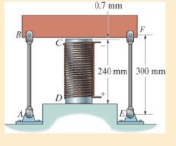
The cylinder CD of the assembly is heated from T1 = 30°C to T2 = 180°C using electrical resistance. At the lower temperature T1 the gap between C and the rigid bar is 0.7 mm. Determine the force in rods AB and EF caused by the increase in temperature. Rods AB and EF are made of steel, and each has a cross-sectional area of 125 mm2. CD is made of aluminum and has a cross-sectional area of 375 mm2. Est = 200 GPa, Eal = 70 GPa, and αal =23(10-6)/°C.
Probs. 4–84/85

Trending nowThis is a popular solution!

Learn your wayIncludes step-by-step video

Chapter 4 Solutions
MECHANICS OF MATERIALS
Additional Engineering Textbook Solutions
Starting Out With Visual Basic (8th Edition)
Starting Out with Java: From Control Structures through Objects (7th Edition) (What's New in Computer Science)
Starting Out with C++ from Control Structures to Objects (9th Edition)
Concepts Of Programming Languages
Degarmo's Materials And Processes In Manufacturing
Java: An Introduction to Problem Solving and Programming (8th Edition)


- 9₁ A Insulated boundary Insulated boundary dx Let's begin with the strong form for a steady-state one-dimensional heat conduction problem, without convection. d dT + Q = dx dx According to Fourier's law of heat conduction, the heat flux q(x), is dT q(x)=-k dx. x Q is the internal heat source, which heat is generated per unit time per unit volume. q(x) and q(x + dx) are the heat flux conducted into the control volume at x and x + dx, respectively. k is thermal conductivity along the x direction, A is the cross-section area perpendicular to heat flux q(x). T is the temperature, and is the temperature gradient. dT dx 1. Derive the weak form using w(x) as the weight function. 2. Consider the following scenario: a 1D block is 3 m long (L = 3 m), with constant cross-section area A = 1 m². The left free surface of the block (x = 0) is maintained at a constant temperature of 200 °C, and the right surface (x = L = 3m) is insulated. Recall that Neumann boundary conditions are naturally satisfied…arrow_forward1 - Clearly identify the system and its mass and energy exchanges between each system and its surroundings by drawing a box to represent the system boundary, and showing the exchanges by input and output arrows. You may want to search and check the systems on the Internet in case you are not familiar with their operations. A pot with boiling water on a gas stove A domestic electric water heater A motor cycle driven on the roadfrom thermodynamics You just need to draw and put arrows on the first part a b and carrow_forward7. A distributed load w(x) = 4x1/3 acts on the beam AB shown in Figure 7, where x is measured in meters and w is in kN/m. The length of the beam is L = 4 m. Find the moment of the resultant force about the point B. w(x) per unit length L Figure 7 Barrow_forward
- 4. The press in Figure 4 is used to crush a small rock at E. The press comprises three links ABC, CDE and BG, pinned to each other at B and C, and to the ground at D and G. Sketch free-body diagrams of each component and hence determine the force exerted on the rock when a vertical force F = 400 N is applied at A. 210 80 80 C F 200 B 80 E 60% -O-D G All dimensions in mm. Figure 4arrow_forward2. Figure 2 shows a device for lifting bricks and concrete blocks. It comprises two compo- nents ABC and BD, with a frictionless pin at B. Determine the minimum coefficient of friction required at A and D if the device is to work satisfactorily. W all dimensions in inches Figure 2 Darrow_forward1. The shaft AD in Figure 1 supports two pulleys at B and C of radius 200 mm and 250 mm respectively. The shaft is supported in frictionless bearings at A and D and is rotating clockwise (when viewed from the right) at a constant speed of 300 rpm. Only bearing A can support thrust. The tensions T₁ = 200 N, T₂ = 400 N, and T3 = 300 N. The distances AB = 120 mm, BC = 150 mm, and CD120 mm. Find the tension 74 and the reaction forces at the bearings. A T fo Figure 1arrow_forward
- 5. Figure 5 shows a two-dimensional idealization of the front suspension system for a car. During cornering, the road exerts a vertical force of 5 kN and a leftward horizontal force of 1.2 kN on the tire, which is of 510 mm diameter. Draw free-body diagrams of each component and determine the forces transmitted between them. 250 A -320 B 170 D 170 -220-220- all dimensions in mm. Figure 5arrow_forward8. The force F in Figure 8 is 120 lb and the angle 0 = 25°. Find the axial force N, the shear force V and the bending moment M at the point K which is midway between B and C and illustrate their directions on a sketch of the segment KCD. E -0 B K అ D H 7 A- all dimensions in inches Figure 8 Ꮎ G Farrow_forward6. Determine the coordinates x, y of the centroid of the area shaded in Figure 6. y y=x³ Figure 6 3arrow_forward
- 3. Use the method of sections to determine the forces in the members BD, CD, CE in the struc- ture of Figure 3. A B D 4 kN 6 kN all dimensions in meters. Figure 3arrow_forwardA pipeline engineer is considering alternative natural gas pipeline routings. The first route is mostly over land and the second is primarily undersea. Both pipelines will need some valve and fitting replacements in year 25. Cost data for each route is shown in Table P2.21. Notice that the undersea route has a higher initial cost due to higher installation costs and extra corrosion protection for the pipeline. However, the undersea route has cheaper security and maintenance costs which substantially reduces annual costs. The MARR for the project is 15%. Determine which route should be pursued based on a present worth analysis.arrow_forwardThe state of stress at a point is σ = -4.00 kpsi, σy Tyz = 8.000 kpsi, and T₂ = -14.00 kpsi. What is the maximum shear stress for this case? The maximum shear stress is kpsi. = 16.00 kpsi, σ = -14.00 kpsi, Try = 11.00 kpsi,arrow_forward
 Elements Of ElectromagneticsMechanical EngineeringISBN:9780190698614Author:Sadiku, Matthew N. O.Publisher:Oxford University Press
 Mechanics of Materials (10th Edition)Mechanical EngineeringISBN:9780134319650Author:Russell C. HibbelerPublisher:PEARSON
 Thermodynamics: An Engineering ApproachMechanical EngineeringISBN:9781259822674Author:Yunus A. Cengel Dr., Michael A. BolesPublisher:McGraw-Hill Education
 Control Systems EngineeringMechanical EngineeringISBN:9781118170519Author:Norman S. NisePublisher:WILEY
 Mechanics of Materials (MindTap Course List)Mechanical EngineeringISBN:9781337093347Author:Barry J. Goodno, James M. GerePublisher:Cengage Learning
 Engineering Mechanics: StaticsMechanical EngineeringISBN:9781118807330Author:James L. Meriam, L. G. Kraige, J. N. BoltonPublisher:WILEY