
EBK MECHANICS OF MATERIALS
10th Edition
ISBN: 8220102744110
Author: HIBBELER
Publisher: PEARSON
expand_more
expand_more
format_list_bulleted
Concept explainers
Videos
Textbook Question
Chapter 4.5, Problem 4.48P
If there are n fibers, each having a cross-sectional area of Af and modulus of Ef1 embedded in a matrix having a cross-sectional area of Am and modulus of Em, determine the stress in the matrix and in each fiber when the force P is applied on the specimen
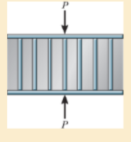
Prob. 4–48
Expert Solution & Answer
Want to see the full answer?
Check out a sample textbook solution
Students have asked these similar questions
=
MMB 241 Tutorial 2.pdf
1 / 3
75%
+ +
Tutorial z
Topic: Kinematics of Particles:-.
QUESTIONS
1. Use the chain-rule and find y and ŷ in terms of x, x and x if
a) y=4x²
b) y=3e
c) y = 6 sin x
2. The particle travels from A to B. Identify the three unknowns, and write the three
equations needed to solve for them.
8 m
10 m/s
30°
B
x
3. The particle travels from A to B. Identify the three unknowns, and write the three
equations needed to solve for them.
A
40 m/s
20 m
B
1
3 m³/s-
1 md
45°
V
1.8 mr
2mr
=
MMB 241 Tutorial 2.pdf
3/3
75%
+ +
6. A particle is traveling along the parabolic path y = 0.25 x². If x = 8 m, vx=8 m/s, and ax=
4 m/s² when t = 2 s, determine the magnitude of the particle's velocity and acceleration at
this instant.
y = 0.25x²
-x
7. Determine the speed at which the basketball at A must be thrown at the angle of 30° so
that it makes it to the basket at B.
30°
-x
1.5 m
B
3 m
-10 m-
8. The basketball passed through the hoop even though it barely cleared the hands of the
player B who attempted to block it. Neglecting the size of the ball, determine the
2
Chapter 4 Solutions
EBK MECHANICS OF MATERIALS
Ch. 4.2 - In each case, determine the internal normal force...Ch. 4.2 - Determine the internal normal force between...Ch. 4.2 - The post weighs 8kN/m. Determine the internal...Ch. 4.2 - The rod is subjected to an external axial force of...Ch. 4.2 - The rigid beam supports the load of 60 kN....Ch. 4.2 - The 20-mm-diameter A-36 steel rod is subjected to...Ch. 4.2 - Segments AB and CD of the assembly are solid...Ch. 4.2 - The 30-mm-diameter A992 steel rod is subjected to...Ch. 4.2 - If the 20-mm-diameter rod is made of A-36 steel...Ch. 4.2 - The 20-mm-diameter 2014-T6 aluminum rod is...
Ch. 4.2 - The 20-mm-diameter 2014-T6 aluminum rod is...Ch. 4.2 - The A992 steel rod is subjected to the loading...Ch. 4.2 - The copper shaft is subjected to the axial loads...Ch. 4.2 - The composite shaft, consisting of aluminum,...Ch. 4.2 - The composite shaft, consisting of aluminum,...Ch. 4.2 - The 2014-T6 aluminium rod has a diameter of 30 mm...Ch. 4.2 - The A-36 steel drill shaft of an oil well extends...Ch. 4.2 - The truss is made of three A-36 steel members,...Ch. 4.2 - The truss is made of three A-36 steel members,...Ch. 4.2 - The assembly consists of two 10-mm diameter red...Ch. 4.2 - The assembly consists of two 10-mm diameter red...Ch. 4.2 - The load is supported by the four 304 stainless...Ch. 4.2 - The load is supported by the four 304 stainless...Ch. 4.2 - The rigid bar is supported by the pin-connected...Ch. 4.2 - The post is made of Douglas fir and has a diameter...Ch. 4.2 - The post is made of Douglas fir and has a diameter...Ch. 4.2 - The coupling rod is subjected to a force of 5 kip....Ch. 4.2 - The pipe is stuck in the ground so that when it is...Ch. 4.2 - The is made of three pin-connected A992 steel...Ch. 4.2 - The linkage is made of three pin connected A992...Ch. 4.2 - The assembly consists of three titanium...Ch. 4.2 - The rigid beam is supported at its ends by two...Ch. 4.2 - The rigid beam is supported at its ends by two...Ch. 4.2 - The steel bar has the original dimensions shown in...Ch. 4.2 - Determine the relative displacement of one end of...Ch. 4.2 - The assembly consists of two rigid bars that are...Ch. 4.2 - The truss consists of three members, each made...Ch. 4.2 - Solve Prob. 426 when the load P acts vertically...Ch. 4.2 - The observation cage C has a weight of 250 kip and...Ch. 4.2 - The steel bar has the original dimensions shown in...Ch. 4.2 - The ball is truncated at its ends and is used to...Ch. 4.5 - The column is constructed from high-strength...Ch. 4.5 - The column is constructed from high-strength...Ch. 4.5 - The A-36 steel pipe has a 6061-T6 aluminum core....Ch. 4.5 - If column AB is made from high strength precast...Ch. 4.5 - If column AB is made from high strength precast...Ch. 4.5 - Determine the support reactions at the rigid...Ch. 4.5 - If the supports at A and C are flexible and have a...Ch. 4.5 - The load of 2000 lb is to be supported by the two...Ch. 4.5 - The load of 2000 lb is to be supported by the two...Ch. 4.5 - The A-36 steel pipe has an outer radius of 20 mm...Ch. 4.5 - The 10-mm-diameter steel bolt is surrounded by a...Ch. 4.5 - The 10-mm-diameter steel bolt is surrounded by a...Ch. 4.5 - The assembly consists of two red brass C83400...Ch. 4.5 - The rigid beam is supported by the three suspender...Ch. 4.5 - The bolt AB has a diameter of 20 mm and passes...Ch. 4.5 - If the gap between C and the rigid wall at D is...Ch. 4.5 - The support consists of a solid red brass C83400...Ch. 4.5 - If there are n fibers, each having a...Ch. 4.5 - The rigid bar is pinned at A and supported by two...Ch. 4.5 - The rigid bar is pinned at A and supported by two...Ch. 4.5 - The rigid bar is pinned at A and supported by two...Ch. 4.5 - The rigid bar is pinned at A and supported by two...Ch. 4.5 - The 2014-T6 aluminum rod AC is reinforced with the...Ch. 4.5 - The 2014-T6 aluminum rod AC is reinforced with the...Ch. 4.5 - The three suspender bars are made of A992 steel...Ch. 4.5 - The three A-36 steel wires each have a diameter of...Ch. 4.5 - The A-36 steel wires AB and AD each have a...Ch. 4.5 - The post is made from 6061-T6 aluminum and has a...Ch. 4.5 - The post is made from 6061-T6 aluminum and has a...Ch. 4.5 - The bracket is held to the wall using three A-36...Ch. 4.5 - The bracket is held to the wall using three A-36...Ch. 4.5 - If each of the posts has an unloaded length of 1 m...Ch. 4.5 - The rigid bar is supported by the two short white...Ch. 4.5 - The assembly consists of two posts AB and CD each...Ch. 4.5 - The assembly consists of two posts AB and CD each...Ch. 4.5 - The assembly consists of two posts AB and CD each...Ch. 4.5 - The wheel is subjected to a force of 18 kN from...Ch. 4.6 - The C83400-red-brass rod AB and 2014-T6- aluminum...Ch. 4.6 - The assembly has the diameters and material...Ch. 4.6 - The rod is made of A992 steel and has a diameter...Ch. 4.6 - The two cylindrical rod segments are fixed to the...Ch. 4.6 - The two cylindrical rod segments are fixed to the...Ch. 4.6 - The pipe is made of A992 steel and is connected to...Ch. 4.6 - The bronze C86100 pipe has an inner radius of 0.5...Ch. 4.6 - The 40-ft-long A-36 steel rails on a train track...Ch. 4.6 - The device is used to measure a change in...Ch. 4.6 - The bar has a cross-sectional area A, length L,...Ch. 4.6 - When the temperature is at 30C, the A-36 steel...Ch. 4.6 - When the temperature is at 30C, the A-36 steel...Ch. 4.6 - When the temperature is at 30C, the A-36 steel...Ch. 4.6 - The 50-mm-diameter cylinder is made from Am...Ch. 4.6 - The 50-mm-diameter cylinder is made from Am...Ch. 4.6 - The wires AB and AC are made of steel, and wire AD...Ch. 4.6 - The cylinder CD of the assembly is heated from T1...Ch. 4.6 - The cylinder CD of the assembly is heated from T1=...Ch. 4.6 - The metal strap has a thickness t and width w and...Ch. 4.9 - Determine the maximum normal stress developed in...Ch. 4.9 - If the allowable normal stress for the bar is...Ch. 4.9 - The steel bar has the dimensions shown. Determine...Ch. 4.9 - The A-36 steel plate has a thickness of 12 mm. If...Ch. 4.9 - Determine the maximum axial force P that can be...Ch. 4.9 - Determine the maximum normal stress developed in...Ch. 4.9 - The member is to be made from a steel plate that...Ch. 4.9 - The resulting stress distribution along section AB...Ch. 4.9 - The resulting stress distribution along section AB...Ch. 4.9 - Prob. 4.96PCh. 4.9 - The weight is suspended from steel and aluminum...Ch. 4.9 - The bar has a cross-sectional area of 0.5 in2 and...Ch. 4.9 - The distributed loading is applied to the rigid...Ch. 4.9 - The distributed loading is applied to the rigid...Ch. 4.9 - The rigid lever arm is supported by two A-36 steel...Ch. 4.9 - The rigid lever arm is supported by two A-36 steel...Ch. 4.9 - The 300-kip weight is slowly set on the top of a...Ch. 4.9 - The rigid beam is supported by three 25-mm...Ch. 4.9 - The rigid beam is supported by three 25-mm...Ch. 4.9 - The rigid beam is supported by the three posts A,...Ch. 4.9 - The rigid beam is supported by the three posts A,...Ch. 4.9 - The bar having a diameter of 2 in. is fixed...Ch. 4.9 - Determine the elongation of the bar in Prob.4108...Ch. 4.9 - The rigid beam is supported by three A-36 steel...Ch. 4 - The assembly consists of two A992 steel bolts AB...Ch. 4 - The assembly shown consists of two A992 steel...Ch. 4 - The rods each have the same 25-mm diameter and...Ch. 4 - Two A992 steel pipes, each having a...Ch. 4 - The force P is applied to the bar, which is made...Ch. 4 - The 2014-T6 aluminum rod has a diameter of 0.5 in....Ch. 4 - The 2014-T6 aluminum rod has a diameter of 0.5 in....Ch. 4 - The rigid link is supported by a pin at A and two...Ch. 4 - The joint is made from three A992 steel plates...
Knowledge Booster


Learn more about
Need a deep-dive on the concept behind this application? Look no further. Learn more about this topic, mechanical-engineering and related others by exploring similar questions and additional content below.Similar questions
- Adhesives distribute loads across the interface, whereas fasteners create areas of localized stresses. True or Falsearrow_forwardA continuous column flash system is separating 100 kmol/h of a saturated liquid feed that is 45 mol% methanol and 55 mol% water at 1.0 atm. Operate with L/V = 1.5 and the outlet bottoms at xN = 0.28. Find the values of FL, FV, y1, and the number of equilibrium stages required. Find the value of Q used to vaporize FV. For a normal flash with the same feed and the same V/F, find the values of x and y.arrow_forwardA beer still is being used to separate ethanol from water at 1.0 atm. The saturated liquid feed flow rate is F = 840.0 kmol/h. The feed is 44.0 mol% ethanol. The saturated vapor steam is pure water with ratio of steam flow rate S to feed rate, S/F = 2/3. We desire a bottoms product that is 4.0 mol% ethanol. CMO is valid. Find the mole fraction of ethanol in the distillate vapor, yD,E. Find the number of equilibrium stages required. If the feed is unchanged and the S/F ratio is unchanged, but the number of stages is increased to a very large number, what is the lowest bottoms mole fraction of ethanol that can be obtained?arrow_forward
- 3.1 Convert the following base-2 numbers to base-10: (a) 1011001, (b) 110.0101, and (c) 0.01011.arrow_forwardConsider the forces acting on the handle of the wrench in (Figure 1). a) Determine the moment of force F1={−F1={−2i+i+ 4 jj −−8k}lbk}lb about the zz axis. Express your answer in pound-inches to three significant figures. b) Determine the moment of force F2={F2={3i+i+ 7 jj −−6k}lbk}lb about the zz axis. Express your answer in pound-inches to three significant figures.arrow_forwardI need you to explain each and every step (Use paper)arrow_forward
- Calculate the Moment About the Point A -20"- 5 lb 40 N D 1.5 m 40 N 4.5 m A 15 lb. 150 mm 52 N 5 12 100 mm 15 lb. 26 lb. 12 5 34 lb. 13 8 15 77777 36 lb.arrow_forwardCalculate the Moment About the Point A -20"- 5 lb 40 N D 1.5 m 40 N 4.5 m A 15 lb. 150 mm 52 N 5 12 100 mm 15 lb. 26 lb. 12 5 34 lb. 13 8 15 77777 36 lb.arrow_forwardFormala for Hunzontal component= + cos & Vertical Component: Fsin t Find the vertical and horizontal components for the figure bellow: 30° 200 N 77 200 cos 30 = 173 N // 200 sin 30 = 100 N YA a₂+b₂ b₂ (b₁,b₂) a+b 20haits (a+b₁,a+b) Magnitude a and b a = lbl = 2o unite rugle of vector a wt Horisontal Axis = 30 11 vector & wt Honzontal Axis - 60° b b a= |a| Cas 30 a2 (a1, a2) ag = 10 bx = /b/ cos a 1 20 cos 80 = 17.32 Sia 30 = 20 sin 30. 60 = 10 = 20 Cos 60 = It by = 161 sin 60 = 20 sia 60 = 17.32 b₁ Rx ax +bx = 17.32 +10=2732 a₁ a₁+b₁ X By = ou + by= + + by = 10 + 17.32 =27.32 Magnitude = 38.637 Find the Vector a +b the Resultans The angle of the vector with the horizontal axle is 30 degrees while the angle of the vector b is 60 degrees. The magnitude of both vectors is 20 (units) angle of the Resultant vector = tam- " (14) 45arrow_forward
- The net force exerted on the piston by the exploding fuel-air mixture and friction is 5 kN to the left. A clockwise couple M = 200 N-m acts on the crank AB. The moment of inertia of the crank about A is 0.0003 kg-m2 . The mass of the connecting rod BC is 0.36 kg, and its center of mass is 40 mm from B on the line from B to C. The connecting rod’s moment of inertia about its center of mass is 0.0004 kg-m2 . The mass of the piston is 4.6 kg. The crank AB has a counterclockwise angular velocity of 2000 rpm at the instant shown. Neglect the gravitational forces on the crank, connecting rod, and piston – they still have mass, just don’t include weight on the FBDs. What is the piston’s acceleration?arrow_forwardSolve only no 1 calculations,the one with diagram,I need handwritten expert solutionsarrow_forwardProblem 3 • Compute the coefficient matrix and the right-hand side of the n-parameter Ritz approximation of the equation d du (1+x)· = 0 for 0 < x < 1 dx dx u (0) = 0, u(1) = 1 Use algebraic polynomials for the approximation functions. Specialize your result for n = 2 and compute the Ritz coefficients.arrow_forward
arrow_back_ios
SEE MORE QUESTIONS
arrow_forward_ios
Recommended textbooks for you
 Elements Of ElectromagneticsMechanical EngineeringISBN:9780190698614Author:Sadiku, Matthew N. O.Publisher:Oxford University Press
 Mechanics of Materials (10th Edition)Mechanical EngineeringISBN:9780134319650Author:Russell C. HibbelerPublisher:PEARSON
 Thermodynamics: An Engineering ApproachMechanical EngineeringISBN:9781259822674Author:Yunus A. Cengel Dr., Michael A. BolesPublisher:McGraw-Hill Education
 Control Systems EngineeringMechanical EngineeringISBN:9781118170519Author:Norman S. NisePublisher:WILEY
 Mechanics of Materials (MindTap Course List)Mechanical EngineeringISBN:9781337093347Author:Barry J. Goodno, James M. GerePublisher:Cengage Learning
 Engineering Mechanics: StaticsMechanical EngineeringISBN:9781118807330Author:James L. Meriam, L. G. Kraige, J. N. BoltonPublisher:WILEY
Elements Of Electromagnetics
Mechanical Engineering
ISBN:9780190698614
Author:Sadiku, Matthew N. O.
Publisher:Oxford University Press
Mechanics of Materials (10th Edition)
Mechanical Engineering
ISBN:9780134319650
Author:Russell C. Hibbeler
Publisher:PEARSON
Thermodynamics: An Engineering Approach
Mechanical Engineering
ISBN:9781259822674
Author:Yunus A. Cengel Dr., Michael A. Boles
Publisher:McGraw-Hill Education
Control Systems Engineering
Mechanical Engineering
ISBN:9781118170519
Author:Norman S. Nise
Publisher:WILEY
Mechanics of Materials (MindTap Course List)
Mechanical Engineering
ISBN:9781337093347
Author:Barry J. Goodno, James M. Gere
Publisher:Cengage Learning
Engineering Mechanics: Statics
Mechanical Engineering
ISBN:9781118807330
Author:James L. Meriam, L. G. Kraige, J. N. Bolton
Publisher:WILEY
Everything About COMBINED LOADING in 10 Minutes! Mechanics of Materials; Author: Less Boring Lectures;https://www.youtube.com/watch?v=N-PlI900hSg;License: Standard youtube license