
Concept explainers
Videos
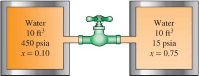
Two 10-ft3 adiabatic tanks are connected by a valve. Initially, one tank contains water at 450 psia with 10 percent quality, while the second contains water at 15 psia with 75 percent quality. The valve is now opened, allowing the water vapor from the high-pressure tank to move to the low-pressure tank until the pressure in the two becomes equal. Determine the final pressure and the final mass in each tank.
FIGURE P4–142E
The final pressure of each tank.
The final mass of each tank.
Answer to Problem 142RP
The final pressure of each tank is
The final mass of each tank is
Explanation of Solution
Write the expression for the energy balance equation.
Here, the total energy entering the system is
Simplify Equation (V) and write energy balance relation of two adiabatic tanks.
Here, the heat to be transfer into the system is
Substitute 0 for
Here, the initial mass of tank A is
Write the expression for initial mass of tank A.
Here, the volume of the tank A is
Write the expression for initial mass of tank B.
Here, the volume of the tank B is
Write the expression for total mass of tank.
Write the expression for initial total internal energy contained in both tanks.
Write the expression for initial is equal to final specific internal energy of tank.
Determine the total volume of both the tanks.
Write the expression for initial is equal to final specific volume of tank.
Write the expression for final mass contained in both tanks.
Conclusion:
At initial pressure and quality of initial state for tank A as 450 psia and 0.10, find the value of initial specific volume and specific internal energy of the tank.
Here, the specific volume of saturated liquid for tank A is
Here, the specific internal energy of saturated liquid for tank A is
Substitute
Substitute
At initial pressure and quality of initial state for tank B as 15 psia and 0.75, find the value of initial specific volume and specific internal energy of the tank.
Here, the specific volume of saturated liquid for tank B is
Here, the specific internal energy of saturated liquid for tank B is
Substitute
Substitute
Substitute
Substitute
Substitute
Substitute
Substitute
Substitute
Substitute
By above calculation from Table A-5E “saturated water” the final pressure of both tanks as
Thus, the final pressure of each tank is
Substitute
Thus, the final mass of each tank is
Want to see more full solutions like this?
Chapter 4 Solutions
THERMODYNAMICS LLF W/ CONNECT ACCESS


- Complet the solution : Vavg Ti Te Ts Q hexp Nuexp htheo Re Nutheo Error (m/s) (*C) (*C) (*C) (W) 2.11 18.8 21.3 45.8 2.61 18.5 20.8 46.3arrow_forwardA 48-kg iron block and a 76-kg copper block, both initially at 80°C, are dropped into a large lake at 15°C. Thermal equilibrium is established after a while as a result of heat transfer between the blocks and the lake water. Determine the total entropy change for this process. The specific heat of iron at room temperature is cp = 0.45 kJ/kg·K. The specific heat of copper at 27°C is cp = 0.386 kJ/kg·K. The total entropy change for this process is kJ/K.arrow_forwardPlease help Air at 4.4 MPa and 500°C is expanded in an adiabatic gas turbine to 0.2 MPa. Calculate the maximum work that this turbine can produce in kJ/kg. Use the table containing the ideal gas specific heats of various common gases. The maximum work that this turbine can produce is kJ/kg.arrow_forward
- Saturated water vapor at 150°C is compressed in a reversible steady-flow device to 1150 kPa while its specific volume remains constant. Determine the work required in kJ/kg. Use steam tables. The work required is kJ/kg.arrow_forwardThree lbm of R-134a is expanded isentropically in a closed system from 100 psia and 100°F to 10 psia. Determine the total heat transfer and the work production for this process. Use the tables for R-134a. The total heat transfer is Btu. The work production for this process is Btu. Three lbm of R-134a is expanded isentropically in a closed system from 100 psia and 100°F to 10 psia. Determine the total heat transfer and the work production for this process. Use the tables for R-134a. The total heat transfer is Btu. The work production for this process is Btu.arrow_forwardOxygen at 300 kPa and 90°C flowing at an average velocity of 3 m/s is expanded in an adiabatic nozzle. What is the maximum velocity of the oxygen at the outlet of this nozzle when the outlet pressure is 60 kPa? Use the table containing the ideal gas specific heats of various common gases. The maximum velocity of the oxygen at the outlet of this nozzle is m/s.arrow_forward
- The well-insulated container shown in the given figure is initially evacuated. The supply line contains air that is maintained at 150 psia and 110°F. The valve is opened until the pressure in the container is the same as the pressure in the supply line. Determine the minimum temperature in the container when the valve is closed. Use the table containing the ideal gas specific heats of various common gases. A valve is shown at the vertical tube. The minimum temperature in the container when the valve is closed is °F.arrow_forwardDuring the isothermal heat addition process of a Carnot cycle, 1050 kJ of heat is added to the working fluid from a source at 400°C. NOTE: This is a multi-part question. Once an answer is submitted, you will be unable to return to this part. Determine the total entropy change for the process. The total entropy change for the process is kJ/K.arrow_forwardQuestion 6 What kind of problem would arise if components of the strain tensor were defined as varrow_forwardplease show steps, thanksarrow_forwardYou design a pin joint. The pin is made of a material with the yield strength of 325 MPa and ultimate strength of 500 MPa. The maximum allowed stress in service is expressed as a tensor 0 100 0 σ 100 0 0 MPa 0 0 Evaluate the safety factor SF for stress in this design. Write answer unitless rounding to 2 decimal places and enter decimals even if those are zeros.arrow_forward2. A single crystal of aluminum is oriented for a tensile test such that its slip plane normal makes an angle of 28.1° with the tensile axis. Three possible slip directions make angles of 62.4°, 72.0°, and 81.1° with the same tensile axis. (a) Which of these three slip directions is most favored? (b) If plastic deformation begins at a tensile stress of σ x = 1.95 MPa (280 psi), determine the critical resolved shear stress for aluminium. (c) If this single crystalspecimen is loaded under the new stress state: σ x =1.2 MPa σ y = -0.8 MPa, and τ xy = 0.6 MPa, howmuch is the resolve the shear stress along the most favored slip direction?arrow_forwardarrow_back_iosSEE MORE QUESTIONSarrow_forward_ios
 Elements Of ElectromagneticsMechanical EngineeringISBN:9780190698614Author:Sadiku, Matthew N. O.Publisher:Oxford University Press
 Mechanics of Materials (10th Edition)Mechanical EngineeringISBN:9780134319650Author:Russell C. HibbelerPublisher:PEARSON
 Thermodynamics: An Engineering ApproachMechanical EngineeringISBN:9781259822674Author:Yunus A. Cengel Dr., Michael A. BolesPublisher:McGraw-Hill Education
 Control Systems EngineeringMechanical EngineeringISBN:9781118170519Author:Norman S. NisePublisher:WILEY
 Mechanics of Materials (MindTap Course List)Mechanical EngineeringISBN:9781337093347Author:Barry J. Goodno, James M. GerePublisher:Cengage Learning
 Engineering Mechanics: StaticsMechanical EngineeringISBN:9781118807330Author:James L. Meriam, L. G. Kraige, J. N. BoltonPublisher:WILEY