
Engineering Mechanics: Statics and Study Pack (13th Edition)
13th Edition
ISBN: 9780133027990
Author: Russell C. Hibbeler
Publisher: Prentice Hall
expand_more
expand_more
format_list_bulleted
Videos
Textbook Question
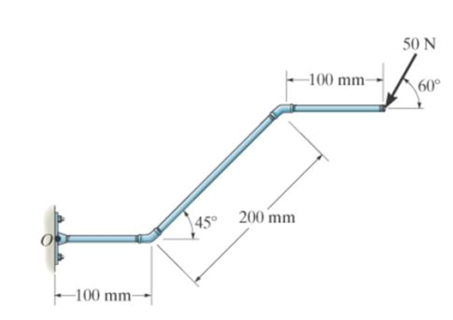
Chapter 4.4, Problem 4FP
Neglect the thickness of the member.
Expert Solution & Answer

Trending nowThis is a popular solution!

Students have asked these similar questions
for the values: M1=0.41m, M2=1.8m, M3=0.56m, please account for these in the equations. also please ensure that the final answer is the flow rate in litres per second for each part. please use bernoullis equation where needed if an empirical solutions i srequired. also The solutions should include, but not be limited to, the equations used tosolve the problems, the charts used to solve the problems, detailed working,choice of variables, the control volume considered, justification anddiscussion of results etc.If determining the friction factor, the use of both Moody chart and empiricalequations should be used to verify the validity of the value
Solve this problem and show all of the work
Solve this problem and show all of the work
Chapter 4 Solutions
Engineering Mechanics: Statics and Study Pack (13th Edition)
Ch. 4.4 - F41. Determine the moment of the force about point...Ch. 4.4 - F42. Determine the moment of the force about point...Ch. 4.4 - F43. Determine the moment of the force about point...Ch. 4.4 - Neglect the thickness of the member.Ch. 4.4 - F45. Determine the moment of the force about point...Ch. 4.4 - F46. Determine the moment of the force about point...Ch. 4.4 - F47. Determine the resultant moment produced by...Ch. 4.4 - F48. Determine the resultant moment produced by...Ch. 4.4 - F49. Determine the resultant moment produced by...Ch. 4.4 - Express the result as a Cartesian vector.
Ch. 4.4 - Express the result as a Cartesian vector.Ch. 4.4 - Express the result as a Cartesian vector.Ch. 4.4 - If A, B, and D are given vectors, prove the...Ch. 4.4 - Prove the triple scalar product identity A (B C)...Ch. 4.4 - Given the three nonzero vectors A, B and C, show...Ch. 4.4 - Determine the moment about point A of each of the...Ch. 4.4 - Determine the moment about point B of each of the...Ch. 4.4 - Prob. 6PCh. 4.4 - Determine the moment of each of the three forces...Ch. 4.4 - Determine the moment of each of the three forces...Ch. 4.4 - Take FB = 40 lb, FC = 50 lb. Probs. 49/10Ch. 4.4 - If FB = 30 lb and FC = 45 lb, determine the...Ch. 4.4 - Prob. 11PCh. 4.4 - Prob. 12PCh. 4.4 - Prob. 13PCh. 4.4 - Prob. 14PCh. 4.4 - Prob. 15PCh. 4.4 - Prob. 16PCh. 4.4 - Prob. 17PCh. 4.4 - The tower crane is used to hoist the 2-Mg load...Ch. 4.4 - The tower crane is used to hoist a 2-Mg load...Ch. 4.4 - The handle of the hammer is subjected to the force...Ch. 4.4 - In order to pull out the nail at B, the force F...Ch. 4.4 - Prob. 22PCh. 4.4 - Prob. 23PCh. 4.4 - Prob. 24PCh. 4.4 - If the 1500-lb boom AB, the 200-lb cage BCD, and...Ch. 4.4 - If the 1500-lb boom AB, the 200-lb cage BCD, and...Ch. 4.4 - Prob. 27PCh. 4.4 - Prob. 28PCh. 4.4 - Prob. 29PCh. 4.4 - A force F having a magnitude of F = 100N acts...Ch. 4.4 - Prob. 31PCh. 4.4 - Prob. 32PCh. 4.4 - Prob. 33PCh. 4.4 - Prob. 34PCh. 4.4 - Using a ring collar, the 75-N force can act in the...Ch. 4.4 - Prob. 36PCh. 4.4 - Prob. 37PCh. 4.4 - Force F acts perpendicular to the inclined plane....Ch. 4.4 - Force F acts perpendicular to the inclined plane....Ch. 4.4 - The pipe assembly is subjected to the 80-N force....Ch. 4.4 - The pipe assembly is subjected to the 80-N force....Ch. 4.4 - Strut AB of the 1-m-diameter hatch door exerts a...Ch. 4.4 - Determine the smallest force F that must be...Ch. 4.4 - Determine the smallest force F that must be...Ch. 4.4 - A force F = {6i 2j + 1k}kN produces a moment of...Ch. 4.4 - The force F = {6i + 8j + 10k}N creates a moment...Ch. 4.5 - F413. Determine the magnitude of the moment of the...Ch. 4.5 - F414. Determine the magnitude of the moment of the...Ch. 4.5 - Prob. 15FPCh. 4.5 - F416. Determine the magnitude of the moment of the...Ch. 4.5 - Express the result as a Cartesian vector.Ch. 4.5 - Prob. 18FPCh. 4.5 - Prob. 47PCh. 4.5 - Prob. 48PCh. 4.5 - Prob. 49PCh. 4.5 - Prob. 50PCh. 4.5 - Determine the moment of this force about the...Ch. 4.5 - Determine the magnitude of the moments of the...Ch. 4.5 - Determine the moment of this force F about an axis...Ch. 4.5 - The board is used to hold the end of a four-way...Ch. 4.5 - The board is used to hold the end of a four-way...Ch. 4.5 - Prob. 56PCh. 4.5 - Prob. 57PCh. 4.5 - Prob. 58PCh. 4.5 - Prob. 59PCh. 4.5 - The force of F = 30 N acts on the bracket as...Ch. 4.5 - Prob. 61PCh. 4.5 - Prob. 62PCh. 4.5 - Prob. 63PCh. 4.5 - Prob. 64PCh. 4.5 - Prob. 65PCh. 4.5 - The A-frame is being hoisted into an upright...Ch. 4.6 - F419. Determine the resultant couple moment acting...Ch. 4.6 - F420. Determine the resultant couple moment acting...Ch. 4.6 - Determine the magnitude of F so that the resultant...Ch. 4.6 - Determine the couple moment acting on the beam.Ch. 4.6 - Determine the resultant couple moment acting on...Ch. 4.6 - Determine the couple moment acting on the pipe...Ch. 4.6 - A twist of 4 N m is applied to the handle of the...Ch. 4.6 - Prob. 68PCh. 4.6 - Prob. 69PCh. 4.6 - Two couples act on the beam. If F = 125 lb,...Ch. 4.6 - Two couples act on the beam. Determine the...Ch. 4.6 - Determine the magnitude of the couple forces so...Ch. 4.6 - The man tries to open the valve by applying the...Ch. 4.6 - If the valve can be opened with a couple moment of...Ch. 4.6 - Prob. 75PCh. 4.6 - Determine the magnitude of the couple forces F so...Ch. 4.6 - Two couples act on the beam as shown. If F = 150...Ch. 4.6 - Two couples act on the beam as shown. Determine...Ch. 4.6 - Prob. 79PCh. 4.6 - Prob. 80PCh. 4.6 - Prob. 81PCh. 4.6 - Prob. 82PCh. 4.6 - Prob. 83PCh. 4.6 - Prob. 84PCh. 4.6 - Prob. 85PCh. 4.6 - Prob. 86PCh. 4.6 - Prob. 87PCh. 4.6 - Prob. 88PCh. 4.6 - Prob. 89PCh. 4.6 - Prob. 90PCh. 4.6 - If F = 80 N, determine the magnitude and...Ch. 4.6 - If the magnitude of the couple moment acting on...Ch. 4.6 - Prob. 93PCh. 4.6 - Prob. 94PCh. 4.6 - If F1 = 100 N, F2 = 120 N, and F3 = 80 N,...Ch. 4.6 - Prob. 96PCh. 4.7 - Replace the leading system by an equivalent...Ch. 4.7 - Prob. 26FPCh. 4.7 - Replace the loading system by an equivalent...Ch. 4.7 - Replace the loading system by an equivalent...Ch. 4.7 - Replace the loading system by an equivalent...Ch. 4.7 - Replace the loading system by an equivalent...Ch. 4.7 - Prob. 97PCh. 4.7 - Prob. 98PCh. 4.7 - Replace the force system acting on the beam by an...Ch. 4.7 - Replace the force system acting on the beam by an...Ch. 4.7 - Replace the force system acting on the post by a...Ch. 4.7 - Prob. 102PCh. 4.7 - Prob. 103PCh. 4.7 - Prob. 104PCh. 4.7 - Prob. 105PCh. 4.7 - Prob. 106PCh. 4.7 - A biomechanical model of the lumbar region of the...Ch. 4.7 - Prob. 108PCh. 4.7 - Prob. 109PCh. 4.7 - The belt passing over the pulley is subjected to...Ch. 4.7 - The belt passing over the pulley is subjected to...Ch. 4.7 - Prob. 112PCh. 4.8 - Replace the loading system by an equivalent...Ch. 4.8 - Replace the loading system by an equivalent...Ch. 4.8 - Replace the loading system by an equivalent...Ch. 4.8 - Replace the loading system by an equivalent...Ch. 4.8 - Replace the loading shown by an equivalent single...Ch. 4.8 - Replace the loading shown by an equivalent single...Ch. 4.8 - The weights of the various components of the truck...Ch. 4.8 - The weights of the various components of the truck...Ch. 4.8 - Prob. 115PCh. 4.8 - Prob. 116PCh. 4.8 - Replace the loading acting on the beam by a single...Ch. 4.8 - Replace the loading acting on the beam by a single...Ch. 4.8 - R46. Replace the force system acting on the frame...Ch. 4.8 - Prob. 120PCh. 4.8 - Prob. 121PCh. 4.8 - Prob. 122PCh. 4.8 - Prob. 123PCh. 4.8 - Replace the force system acting on the post by a...Ch. 4.8 - Replace the force system acting on the post by a...Ch. 4.8 - Prob. 126PCh. 4.8 - The tube supports the four parallel forces....Ch. 4.8 - Prob. 128PCh. 4.8 - Prob. 129PCh. 4.8 - Determine the equivalent resultant force and...Ch. 4.8 - Prob. 131PCh. 4.8 - If FA= 40 kN and FB = 35 kN, determine the...Ch. 4.8 - Prob. 133PCh. 4.8 - Replace the two wrenches and the force, acting on...Ch. 4.8 - Prob. 135PCh. 4.8 - Prob. 136PCh. 4.8 - Prob. 137PCh. 4.9 - Determine the resultant force and specify where it...Ch. 4.9 - Determine the resultant force and specify where it...Ch. 4.9 - Determine the resultant force and specify where it...Ch. 4.9 - Determine the resultant force and specify where it...Ch. 4.9 - Determine the resultant force and specify where it...Ch. 4.9 - Determine the resultant force and specify where it...Ch. 4.9 - Prob. 138PCh. 4.9 - Replace the distributed loading with an equivalent...Ch. 4.9 - Prob. 140PCh. 4.9 - Prob. 141PCh. 4.9 - Prob. 142PCh. 4.9 - Prob. 143PCh. 4.9 - The distribution of soil loading on the bottom of...Ch. 4.9 - R48. Replace the distributed loading by an...Ch. 4.9 - Prob. 146PCh. 4.9 - Prob. 147PCh. 4.9 - Prob. 148PCh. 4.9 - Prob. 149PCh. 4.9 - Replace the loading by an equivalent force and...Ch. 4.9 - Prob. 151PCh. 4.9 - Prob. 152PCh. 4.9 - Prob. 153PCh. 4.9 - Prob. 154PCh. 4.9 - Prob. 155PCh. 4.9 - Prob. 156PCh. 4.9 - Prob. 157PCh. 4.9 - Replace the distributed loading with an equivalent...Ch. 4.9 - Wet concrete exerts a pressure distribution along...Ch. 4.9 - Prob. 160PCh. 4.9 - Prob. 161PCh. 4.9 - Prob. 162PCh. 4.9 - Prob. 163RPCh. 4.9 - Prob. 164RPCh. 4.9 - Prob. 165RPCh. 4.9 - Prob. 166RPCh. 4.9 - R42. Replace the force F having a magnitude of F =...Ch. 4.9 - Prob. 168RPCh. 4.9 - Prob. 169RPCh. 4.9 - Prob. 170RPCh. 4.9 - Prob. 171RPCh. 4.9 - and mass center at G. If the maximum moment that...Ch. 4.9 - Prob. 173RP
Additional Engineering Textbook Solutions
Find more solutions based on key concepts
What is an uninitialized variable?
Starting Out with Programming Logic and Design (5th Edition) (What's New in Computer Science)
The job of the _____ is to fetch instructions, carry out the operations commanded by the instructions, and prod...
Starting Out With Visual Basic (8th Edition)
CONCEPT QUESTIONS
15.CQ3 The ball rolls without slipping on the fixed surface as shown. What is the direction ...
Vector Mechanics for Engineers: Statics and Dynamics
The solid steel shaft AC has a diameter of 25 mm and is supported by smooth bearings at D and E. It is coupled ...
Mechanics of Materials (10th Edition)
Why is the study of database technology important?
Database Concepts (8th Edition)
How is the hydrodynamic entry length defined for flow in a pipe? Is the entry length longer in laminar or turbu...
Fluid Mechanics: Fundamentals and Applications
Knowledge Booster


Learn more about
Need a deep-dive on the concept behind this application? Look no further. Learn more about this topic, mechanical-engineering and related others by exploring similar questions and additional content below.Similar questions
- Problem 2: An athlete, starting from rest, pulls handle A to the left with a constant force of P = 150 [N]. Knowing that after the handle A has been pulled 0.5 [m], its velocity is 5 [m/s] to the left, determine: a) A position constraint equation using the given coordinate system. b) An acceleration constraint equation. c) The acceleration of A using kinematics equations. d) The acceleration of B using your constraint equation. e) How much weight (magnitude) the athlete is lifting in pounds using Newton's 2nd Law. You must draw a FBD and KD of the circled assembly, assuming the pulleys are massless. Note: 1 [lbf] = 4.448 [N]. ХА Увarrow_forwardProblem 1: For each of the following images, draw a complete FBD and KD for the specified objects. Then write the equations of motion using variables for all unknowns (e.g., mass, friction coefficient, etc.), plugging in kinematic expressions and simplifying where appropriate. Assume motion in all cases, so any friction would be kinetic. M (a) Blocks A & B (Be careful with acceleration of B relative to accelerating block A) 30° (b) Block A being pulled up my motor M (use rotated rectangular coordinate system) 20° (c) Ball at C, top of swing (use path coordinates) (d) Parasailer/Person (use polar coordinates)arrow_forwardwhere M1=0.41m, M2=1.8m, M3=0.56m, please use bernoulis equation where necessary and The solutions should include, but not be limited to, the equations used tosolve the problems, the charts used to solve the problems, detailed working,choice of variables, the control volume considered, justification anddiscussion of results etc.If determining the friction factor, the use of both Moody chart and empiricalequations should be used to verify the validity of the value.arrow_forward
- Q3. The attachment shown in Fig.2 is made of 1040 HR. Design the weldment (give the pattern, electrode number, type of weld, length of weld, and leg size). All dimensions in mm 120 Fig.2 12 17 b =7.5 5 kN 60 60°arrow_forward15 mm DA 100 mm 50 mm Assuming the load applied P 80 kN. Determine the maximum stress in the bar shown assuming the diameter of the whole A is DA = 25 mm.arrow_forwarduse engineering economic tables, show full solutionarrow_forward
- Do not use chatgpt. I need quick handwritten solution.arrow_forwardSolve this problem and show all of the workarrow_forwardarch Moving to año Question 5 The head-vs-capacity curves for two centrifugal pumps A and B are shown below: Which of the following is a correct statement at a flow rate of 600 ft3/min? Assuming a pump efficiency of 80%. Head [ft] 50 45. 40 CHE 35. 30 25 20 PR 64°F Cloudy 4arrow_forward
- I need help with a MATLAB code. I am trying to implement algorithm 3 and 4 as shown in the image. I am getting some size errors. Can you help me fix the code. clc; clear all; % Define initial conditions and parameters r0 = [1000, 0, 0]; % Initial position in meters v0 = [0, 10, 0]; % Initial velocity in m/s m0 = 1000; % Initial mass in kg z0 = log(m0); % Initial mass logarithm a0 = [0, 0, 1]; % Initial thrust direction in m/s^2 (thrust in z-direction) sigma0 = 0.1; % Initial thrust magnitude divided by mass % Initial state vector x0 = [r0, v0, z0] x0 = [r0, v0, z0]; % Initial control input u0 = [a0, sigma0] u0 = [a0, sigma0]; % Time span for integration t0 = 0; % Initial time tf = 10; % Final time N = 100; % Number of time steps dt = (tf - t0) / N; % Time step size t_span = linspace(t0, tf, N); % Discretized time vector % Solve the system of equations using ode45 [t, Y] = ode45(@(t, Y) EoMwithDiscreteMatrix(t, Y, u0, x0, t0, tf), t_span, x0); % Compute the matrices A_k,…arrow_forwardQ2) Determine the thickness of weld (h) for the figure shown below. when the Su= 410 MPa and factor of safety of 2. COR 50 200 60 F=2000Narrow_forwardPlease draw front, top and side view, in AutoCAD both of themarrow_forward
arrow_back_ios
SEE MORE QUESTIONS
arrow_forward_ios
Recommended textbooks for you
 Refrigeration and Air Conditioning Technology (Mi...Mechanical EngineeringISBN:9781305578296Author:John Tomczyk, Eugene Silberstein, Bill Whitman, Bill JohnsonPublisher:Cengage Learning
 Welding: Principles and Applications (MindTap Cou...Mechanical EngineeringISBN:9781305494695Author:Larry JeffusPublisher:Cengage Learning
Refrigeration and Air Conditioning Technology (Mi...
Mechanical Engineering
ISBN:9781305578296
Author:John Tomczyk, Eugene Silberstein, Bill Whitman, Bill Johnson
Publisher:Cengage Learning
Welding: Principles and Applications (MindTap Cou...
Mechanical Engineering
ISBN:9781305494695
Author:Larry Jeffus
Publisher:Cengage Learning
Everything About TRANSVERSE SHEAR in 10 Minutes!! - Mechanics of Materials; Author: Less Boring Lectures;https://www.youtube.com/watch?v=4x0E9yvzfCM;License: Standard Youtube License