
Engineering Mechanics: Statics and Modified Mastering Engineering with eText and Access Card (14th Edition)
14th Edition
ISBN: 9780134229287
Author: Russell C. Hibbeler
Publisher: PEARSON
expand_more
expand_more
format_list_bulleted
Videos
Textbook Question
Chapter 4.4, Problem 45P
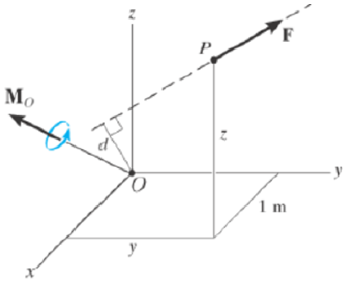
A force F = {6i − 2j + 1k}kN produces a moment of M0 = {4i + 5j −14k}kN·m about the origin point O. If the force acts at a point having an x coordinate of x = 1m, determine the y and z coordinates. Note: The figure shows F and MO is an arbitrary position.
Expert Solution & Answer
Want to see the full answer?
Check out a sample textbook solution
Students have asked these similar questions
The heated rod from Problem 3 is subject to a volumetric heating
h(x) = h0
x
L in units of [Wm−3], as shown in the figure below. Under the
heat supply the temperature of the rod changes along x with the
temperature function T (x). The temperature T (x) is governed by the
d
following equations:
−
dx (q(x)) + h(x) = 0 PDE
q(x) =−k dT
dx Fourier’s law of heat conduction (4)
where q(x) is the heat flux through the rod and k is the (constant)
thermal conductivity. Both ends of the bar are in contact with a heat
reservoir at zero temperature.
Determine:
1. Appropriate BCs for this physical problem.
2. The temperature function T (x).
3. The heat flux function q(x).
Side Note: Please see that both ends of bar are in contact with a heat reservoir at zero temperature so the boundary condition at the right cannot be du/dx=0 because its not thermally insulated. Thank you
The elastic bar from Problem 1 spins with angular velocity ω about an axis, as shown in the figure below. The radial acceleration at a generic point x along the bar is a(x) = ω2x. Under this radial acceleration, the bar stretches along x with displacement function u(x). The displacement d u(x) is governed by the following equations: dx (σ(x)) + ρa(x) = 0 PDE σ(x) = E du dx Hooke’s law (2) where σ(x) is the axial stress in the rod, ρ is the mass density, and E is the (constant) Young’s modulus. The bar is pinned on the rotation axis at x = 0 and it is also pinned at x = L. Determine: 1. Appropriate BCs for this physical problem. 2. The displacement function u(x). 3. The stress function σ(x). SIDE QUESTION: I saw a tutor solve it before but I didn't understand why the tutor did not divide E under the second term (c1x) before finding u(x). The tutor only divided E under first term. please explain and thank you
calculate the total power required to go 80 mph in a VW Type 2 Samba Bus weighing 2310 lbs. with a Cd of 0.35 and a frontal area of 30ft^2. Consider the coefficient of rolling resistance to be 0.018. What is the increase in power required to go the same speed if the weight is increased by 2205 pounds (the rated carrying capacity of the vehicle). If the rated power for the vehicle is 49 bhp, will the van be able to reach 80 mph at full carrying capacity?
Chapter 4 Solutions
Engineering Mechanics: Statics and Modified Mastering Engineering with eText and Access Card (14th Edition)
Ch. 4.4 - P41. In each case, determine the moment of the...Ch. 4.4 - P42. In each case, set up the determinant to find...Ch. 4.4 - F41. Determine the moment of the force about point...Ch. 4.4 - F42. Determine the moment of the force about point...Ch. 4.4 - F43. Determine the moment of the force about point...Ch. 4.4 - Neglect the thickness of the member.Ch. 4.4 - F45. Determine the moment of the force about point...Ch. 4.4 - F46. Determine the moment of the force about point...Ch. 4.4 - F47. Determine the resultant moment produced by...Ch. 4.4 - F48. Determine the resultant moment produced by...
Ch. 4.4 - F49. Determine the resultant moment produced by...Ch. 4.4 - Express the result as a Cartesian vector.Ch. 4.4 - Express the result as a Cartesian vector.Ch. 4.4 - Express the result as a Cartesian vector.Ch. 4.4 - If A, B, and D are given vectors, prove the...Ch. 4.4 - Prove the triple scalar product identity A (B C)...Ch. 4.4 - Given the three nonzero vectors A, B and C, show...Ch. 4.4 - Determine the moment about point A of each of the...Ch. 4.4 - Determine the moment about point B of each of the...Ch. 4.4 - Find the moment of each force about point A and...Ch. 4.4 - Determine the moment of each of the three forces...Ch. 4.4 - Determine the moment of each of the three forces...Ch. 4.4 - Take FB = 40 lb, FC = 50 lb. Probs. 49/10Ch. 4.4 - If FB = 30 lb and FC = 45 lb, determine the...Ch. 4.4 - What is this moment?Ch. 4.4 - If x = 10 m, determine the position of the boom...Ch. 4.4 - What is the moment of this force about point B....Ch. 4.4 - Determine the moment of this force about point O....Ch. 4.4 - Determine the moment of each force about A. Which...Ch. 4.4 - If the man at B exerts a force of P = 30 lb on his...Ch. 4.4 - The mechanic reads the torque on the scale at B....Ch. 4.4 - Determine the torque (moment) MP that the applied...Ch. 4.4 - The tongs are used to grip the ends of the...Ch. 4.4 - The handle of the hammer is subjected to the force...Ch. 4.4 - In order to pull out the nail at B, the force F...Ch. 4.4 - The purpose of the fusee is to increase the...Ch. 4.4 - The tower crane is used to hoist the 2-Mg load...Ch. 4.4 - The tower crane is used to hoist a 2-Mg load...Ch. 4.4 - If the 1500-lb boom AB, the 200-lb cage BCD, and...Ch. 4.4 - If the 1500-lb boom AB, the 200-lb cage BCD, and...Ch. 4.4 - Determine the moment of the force F about point O....Ch. 4.4 - Express the result as a Cartesian vector.Ch. 4.4 - The force F = {400i 100j 700k} lb acts at the...Ch. 4.4 - The force F = {400i 100j 700k} lb acts at the end...Ch. 4.4 - Determine the moment of the force F about point P....Ch. 4.4 - The pipe assembly is subjected to the force of F =...Ch. 4.4 - The pipe assembly is subjected to the force of F =...Ch. 4.4 - Determine the moment of the force of F = 600 N...Ch. 4.4 - Determine the smallest force F that must be...Ch. 4.4 - Determine the coordinate direction angles , , of...Ch. 4.4 - Determine the moment of force F about point O. The...Ch. 4.4 - Determine the moment of the force F about the door...Ch. 4.4 - Determine the moment of the force F about the door...Ch. 4.4 - Determine the smallest force F that must be...Ch. 4.4 - Determine the smallest force F that must be...Ch. 4.4 - A 20-N horizontal force is applied perpendicular...Ch. 4.4 - The pipe assembly is subjected to the 80-N force....Ch. 4.4 - The pipe assembly is subjected to the 80-N force....Ch. 4.4 - A force F = {6i 2j + 1k}kN produces a moment of...Ch. 4.4 - The force F = {6i + 8j + 10k}N creates a moment...Ch. 4.4 - A force F having a magnitude of F = 100N acts...Ch. 4.4 - Force F acts perpendicular to the inclined plane....Ch. 4.4 - Force F acts perpendicular to the inclined plane....Ch. 4.4 - Strut AB of the 1-m-diameter hatch door exerts a...Ch. 4.4 - Using a ring collar, the 75-N force can act in the...Ch. 4.5 - P43. In each case, determine the resultant moment...Ch. 4.5 - P44. In each case, set up the determinant needed...Ch. 4.5 - F413. Determine the magnitude of the moment of the...Ch. 4.5 - F414. Determine the magnitude of the moment of the...Ch. 4.5 - Prob. 15FPCh. 4.5 - F416. Determine the magnitude of the moment of the...Ch. 4.5 - Express the result as a Cartesian vector.Ch. 4.5 - Prob. 18FPCh. 4.5 - The lug nut on the wheel of the automobile is to...Ch. 4.5 - Solve Prob. 4-52 if the cheater pipe AB is slipped...Ch. 4.5 - The A-frame is being hoisted into an upright...Ch. 4.5 - The A-frame is being hoisted into an upright...Ch. 4.5 - Determine the magnitude of the moments of the...Ch. 4.5 - Determine the moment of this force F about an axis...Ch. 4.5 - The board is used to hold the end of a four-way...Ch. 4.5 - The board is used to hold the end of a four-way...Ch. 4.5 - The A-frame is being hoisted into an upright...Ch. 4.5 - Determine the magnitude of the moment of the force...Ch. 4.5 - Determine the magnitude of the moment of the force...Ch. 4.5 - Determine the magnitude of the moment of the force...Ch. 4.5 - A horizontal force of F = {50i} N is applied...Ch. 4.5 - Determine the magnitude of the horizontal force F...Ch. 4.5 - The force of F = 30 N acts on the bracket as...Ch. 4.6 - F419. Determine the resultant couple moment acting...Ch. 4.6 - F420. Determine the resultant couple moment acting...Ch. 4.6 - Determine the magnitude of F so that the resultant...Ch. 4.6 - Determine the couple moment acting on the beam.Ch. 4.6 - Determine the resultant couple moment acting on...Ch. 4.6 - Determine the couple moment acting on the pipe...Ch. 4.6 - A clockwise couple M = 5 N m is resisted by the...Ch. 4.6 - A twist of 4 N m is applied to the handle of the...Ch. 4.6 - If the resultant couple of the three couples...Ch. 4.6 - Two couples act on the beam. If F = 125 lb,...Ch. 4.6 - Two couples act on the beam. Determine the...Ch. 4.6 - Determine the magnitude of the couple forces F so...Ch. 4.6 - The ends of the triangular plate are subjected to...Ch. 4.6 - The man tries to open the valve by applying the...Ch. 4.6 - If the valve can be opened with a couple moment of...Ch. 4.6 - Determine the magnitude of F so that the resultant...Ch. 4.6 - Two couples act on the beam as shown. If F = 150...Ch. 4.6 - Two couples act on the beam as shown. Determine...Ch. 4.6 - Two couples act on the frame. If the resultant...Ch. 4.6 - Two couples act on the frame. If d = 4 ft...Ch. 4.6 - Two couples act on the frame. If d = 4 ft,...Ch. 4.6 - Express the moment of the couple acting on the...Ch. 4.6 - If M1 = 180 lb ft, M2 = 90 lb ft, and M3 = 120...Ch. 4.6 - Determine the magnitudes of couple moments M1, M2,...Ch. 4.6 - The gears are subjected to the couple moments...Ch. 4.6 - Prob. 86PCh. 4.6 - Determine the resultant couple moment of the two...Ch. 4.6 - Express the moment of the couple acting on the...Ch. 4.6 - In order to turn over the frame, a couple moment...Ch. 4.6 - Express the moment of the couple acting on the...Ch. 4.6 - If the couple moment acting on the pipe has a...Ch. 4.6 - If F = 80 N, determine the magnitude and...Ch. 4.6 - If the magnitude of the couple moment acting on...Ch. 4.6 - Express the moment of the couple acting on the rod...Ch. 4.6 - If F1 = 100 N, F2 = 120 N, and F3 = 80 N,...Ch. 4.6 - Prob. 96PCh. 4.7 - P45. In each case, determine the x and y...Ch. 4.7 - Replace the leading system by an equivalent...Ch. 4.7 - Prob. 26FPCh. 4.7 - Replace the loading system by an equivalent...Ch. 4.7 - Replace the loading system by an equivalent...Ch. 4.7 - Replace the loading system by an equivalent...Ch. 4.7 - Replace the loading system by an equivalent...Ch. 4.7 - Replace the force system by an equivalent...Ch. 4.7 - Replace the force system by an equivalent...Ch. 4.7 - Replace the force system acting on the beam by an...Ch. 4.7 - Replace the force system acting on the beam by an...Ch. 4.7 - Replace the loading system acting on the beam by...Ch. 4.7 - Replace the loading system acting on the post by...Ch. 4.7 - Replace the loading system acting on the post by...Ch. 4.7 - Replace the force system acting on the post by a...Ch. 4.7 - Replace the force system acting on the frame by an...Ch. 4.7 - The forces F1 = {4i + 2j 3k) kN and F2 = {3i 4j...Ch. 4.7 - A biomechanical model of the lumbar region of the...Ch. 4.7 - Replace the force system by an equivalent...Ch. 4.7 - Replace the loading by an equivalent resultant...Ch. 4.7 - Replace the force of F = 80 N acting on the pipe...Ch. 4.7 - The belt passing over the pulley is subjected to...Ch. 4.7 - The belt passing over the pulley is subjected to...Ch. 4.8 - P46. In each case, determine the x and y...Ch. 4.8 - P47. In each case, determine the resultant force...Ch. 4.8 - Replace the loading system by an equivalent...Ch. 4.8 - Replace the loading system by an equivalent...Ch. 4.8 - Replace the loading system by an equivalent...Ch. 4.8 - Replace the loading system by an equivalent...Ch. 4.8 - Replace the loading shown by an equivalent single...Ch. 4.8 - Replace the loading shown by an equivalent single...Ch. 4.8 - The weights of the various components of the truck...Ch. 4.8 - The weights of the various components of the truck...Ch. 4.8 - Prob. 115PCh. 4.8 - Prob. 116PCh. 4.8 - Replace the loading acting on the beam by a single...Ch. 4.8 - Replace the loading acting on the beam by a single...Ch. 4.8 - Replace the loading on the frame by a single...Ch. 4.8 - Replace the loading on the frame by a single...Ch. 4.8 - Replace the loading on the frame by a single...Ch. 4.8 - Replace the force system acting on the post by a...Ch. 4.8 - Replace the force system acting on the post by a...Ch. 4.8 - Replace the parallel force system acting on the...Ch. 4.8 - Replace the force and couple system acting on the...Ch. 4.8 - Replace the force and couple system acting on the...Ch. 4.8 - Prob. 127PCh. 4.8 - Determine the magnitudes of FA and FB so that the...Ch. 4.8 - The tube supports the four parallel forces....Ch. 4.8 - The building slab is subjected to four parallel...Ch. 4.8 - The building slab is subjected to four parallel...Ch. 4.8 - If FA= 40 kN and FB = 35 kN, determine the...Ch. 4.8 - Prob. 133PCh. 4.8 - Replace the two wrenches and the force, acting on...Ch. 4.8 - Replace the force system by a wrench and specify...Ch. 4.8 - Replace the five forces acting on the plate by a...Ch. 4.8 - Replace the three forces acting on the plate by a...Ch. 4.9 - Determine the resultant force and specify where it...Ch. 4.9 - Determine the resultant force and specify where it...Ch. 4.9 - Determine the resultant force and specify where it...Ch. 4.9 - Determine the resultant force and specify where it...Ch. 4.9 - Determine the resultant force and specify where it...Ch. 4.9 - Determine the resultant force and specify where it...Ch. 4.9 - Replace the loading by an equivalent resultant...Ch. 4.9 - Replace the distributed loading with an equivalent...Ch. 4.9 - Replace the loading by an equivalent resultant...Ch. 4.9 - Currently eighty-five percent of all neck injuries...Ch. 4.9 - Replace the distributed loading by an equivalent...Ch. 4.9 - Replace this loading by an equivalent resultant...Ch. 4.9 - The distribution of soil loading on the bottom of...Ch. 4.9 - Replace the loading by an equivalent resultant...Ch. 4.9 - Replace the distributed loading by an equivalent...Ch. 4.9 - Determine the length b of the triangular load and...Ch. 4.9 - The form is used to cast a concrete wall having a...Ch. 4.9 - Prob. 149PCh. 4.9 - Replace the loading by an equivalent force and...Ch. 4.9 - Prob. 151PCh. 4.9 - Replace the loading by an equivalent resultant...Ch. 4.9 - Replace the leading by a single resultant force,...Ch. 4.9 - Replace the distributed loading by an equivalent...Ch. 4.9 - Prob. 155PCh. 4.9 - Determine the length b of the triangular load and...Ch. 4.9 - Determine the equivalent resultant force and...Ch. 4.9 - Determine the magnitude of the equivalent...Ch. 4.9 - The distributed load acts on the shaft as shown....Ch. 4.9 - Replace the distributed loading with an equivalent...Ch. 4.9 - Prob. 161PCh. 4.9 - Wet concrete exerts a pressure distribution along...Ch. 4.9 - and mass center at G. If the maximum moment that...Ch. 4.9 - R42. Replace the force F having a magnitude of F =...Ch. 4.9 - Determine the moment of this force about the...Ch. 4.9 - Determine the magnitude of the couple forces so...Ch. 4.9 - Prob. 5RPCh. 4.9 - R46. Replace the force system acting on the frame...Ch. 4.9 - Determine the equivalent resultant force and...Ch. 4.9 - R48. Replace the distributed loading by an...
Knowledge Booster


Learn more about
Need a deep-dive on the concept behind this application? Look no further. Learn more about this topic, mechanical-engineering and related others by exploring similar questions and additional content below.Similar questions
- A distillation column with a total of 13 actual stages (including a partial condenser) is used to perform a separation which requires 7 ideal stages. Calculate the overall column efficiency, and report your answer in %arrow_forward6. Consider a 10N step input to the mechanical system shown below, take M = 15kg, K = 135N/m, and b = 0.4 Ns/m. (a) Assume zero initial condition, calculate the (i) System pole (ii) System characterization, and (iii) The time domain response (b) Calculate the steady-state value of the system b [ www K 个 х M -F(+)arrow_forward2. Solve the following linear time invariant differential equations using Laplace transforms subject to different initial conditions (a) y-y=t for y(0) = 1 and y(0) = 1 (b) ÿ+4y+ 4y = u(t) for y(0) = 0 and y(0) = 1 (c) y-y-2y=0 for y(0) = 1 and y(0) = 0arrow_forward
- 3. For the mechanical systems shown below, the springs are undeflected when x₁ = x2 = x3 = 0 and the input is given as fa(t). Draw the free-body diagrams and write the modeling equations governing each of the systems. K₁ 000 K₂ 000 M₁ M2 -fa(t) B₂ B₁ (a) fa(t) M2 K₂ 000 B K₁ x1 000 M₁ (b)arrow_forwardThis question i m uploading second time . before you provide me incorrect answer. read the question carefully and solve accordily.arrow_forward1. Create a table comparing five different analogous variables for translational, rotational, electrical and fluid systems. Include the standard symbols for each variable in their respective systems.arrow_forward
- 2) Suppose that two unequal masses m₁ and m₂ are moving with initial velocities v₁ and v₂, respectively. The masses hit each other and have a coefficient of restitution e. After the impact, mass 1 and 2 head to their respective gaps at angles a and ẞ, respectively. Derive expressions for each of the angles in terms of the initial velocities and the coefficient of restitution. m1 m2 8 m1 m2 βarrow_forward4. Find the equivalent spring constant and equivalent viscous-friction coefficient for the systems shown below. @ B₁ B₂ H B3 (b)arrow_forward5. The cart shown below is inclined 30 degrees with respect to the horizontal. At t=0s, the cart is released from rest (i.e. with no initial velocity). If the air resistance is proportional to the velocity squared. Analytically determine the initial acceleration and final or steady-state velocity of the cart. Take M= 900 kg and b 44.145 Ns²/m². Mg -bx 2 отarrow_forward
- 9₁ A Insulated boundary Insulated boundary dx Let's begin with the strong form for a steady-state one-dimensional heat conduction problem, without convection. d dT + Q = dx dx According to Fourier's law of heat conduction, the heat flux q(x), is dT q(x)=-k dx. x Q is the internal heat source, which heat is generated per unit time per unit volume. q(x) and q(x + dx) are the heat flux conducted into the control volume at x and x + dx, respectively. k is thermal conductivity along the x direction, A is the cross-section area perpendicular to heat flux q(x). T is the temperature, and is the temperature gradient. dT dx 1. Derive the weak form using w(x) as the weight function. 2. Consider the following scenario: a 1D block is 3 m long (L = 3 m), with constant cross-section area A = 1 m². The left free surface of the block (x = 0) is maintained at a constant temperature of 200 °C, and the right surface (x = L = 3m) is insulated. Recall that Neumann boundary conditions are naturally satisfied…arrow_forward1 - Clearly identify the system and its mass and energy exchanges between each system and its surroundings by drawing a box to represent the system boundary, and showing the exchanges by input and output arrows. You may want to search and check the systems on the Internet in case you are not familiar with their operations. A pot with boiling water on a gas stove A domestic electric water heater A motor cycle driven on the roadfrom thermodynamics You just need to draw and put arrows on the first part a b and carrow_forward7. A distributed load w(x) = 4x1/3 acts on the beam AB shown in Figure 7, where x is measured in meters and w is in kN/m. The length of the beam is L = 4 m. Find the moment of the resultant force about the point B. w(x) per unit length L Figure 7 Barrow_forward
arrow_back_ios
SEE MORE QUESTIONS
arrow_forward_ios
Recommended textbooks for you
 Elements Of ElectromagneticsMechanical EngineeringISBN:9780190698614Author:Sadiku, Matthew N. O.Publisher:Oxford University Press
 Mechanics of Materials (10th Edition)Mechanical EngineeringISBN:9780134319650Author:Russell C. HibbelerPublisher:PEARSON
 Thermodynamics: An Engineering ApproachMechanical EngineeringISBN:9781259822674Author:Yunus A. Cengel Dr., Michael A. BolesPublisher:McGraw-Hill Education
 Control Systems EngineeringMechanical EngineeringISBN:9781118170519Author:Norman S. NisePublisher:WILEY
 Mechanics of Materials (MindTap Course List)Mechanical EngineeringISBN:9781337093347Author:Barry J. Goodno, James M. GerePublisher:Cengage Learning
 Engineering Mechanics: StaticsMechanical EngineeringISBN:9781118807330Author:James L. Meriam, L. G. Kraige, J. N. BoltonPublisher:WILEY
Elements Of Electromagnetics
Mechanical Engineering
ISBN:9780190698614
Author:Sadiku, Matthew N. O.
Publisher:Oxford University Press
Mechanics of Materials (10th Edition)
Mechanical Engineering
ISBN:9780134319650
Author:Russell C. Hibbeler
Publisher:PEARSON
Thermodynamics: An Engineering Approach
Mechanical Engineering
ISBN:9781259822674
Author:Yunus A. Cengel Dr., Michael A. Boles
Publisher:McGraw-Hill Education
Control Systems Engineering
Mechanical Engineering
ISBN:9781118170519
Author:Norman S. Nise
Publisher:WILEY
Mechanics of Materials (MindTap Course List)
Mechanical Engineering
ISBN:9781337093347
Author:Barry J. Goodno, James M. Gere
Publisher:Cengage Learning
Engineering Mechanics: Statics
Mechanical Engineering
ISBN:9781118807330
Author:James L. Meriam, L. G. Kraige, J. N. Bolton
Publisher:WILEY
How to balance a see saw using moments example problem; Author: Engineer4Free;https://www.youtube.com/watch?v=d7tX37j-iHU;License: Standard Youtube License