
Engineering Mechanics: Statics and Modified Mastering Engineering with eText and Access Card (14th Edition)
14th Edition
ISBN: 9780134229287
Author: Russell C. Hibbeler
Publisher: PEARSON
expand_more
expand_more
format_list_bulleted
Videos
Textbook Question
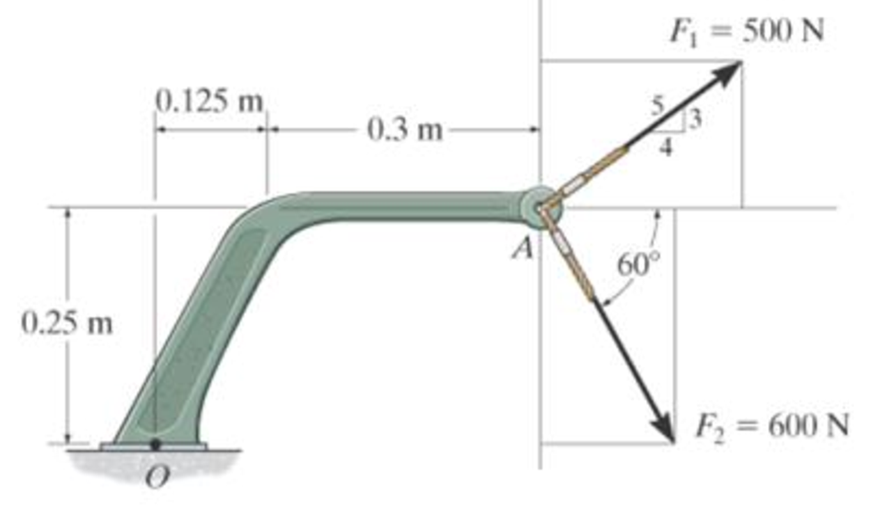
Chapter 4.4, Problem 8FP
F4–8. Determine the resultant moment produced by the forces about point O.
Expert Solution & Answer

Learn your wayIncludes step-by-step video

schedule03:24
Students have asked these similar questions
1 - Clearly identify the system and its mass and energy exchanges between each system and its surroundings by drawing a box to represent the system boundary, and showing the exchanges by input and output arrows. You may want to search and check the systems on the Internet in case you are not familiar with their operations.
A pot with boiling water on a gas stove
A domestic electric water heater
A motor cycle driven on the roadfrom thermodynamics
You just need to draw and put arrows on the first part a b and c
7. A distributed load
w(x) = 4x1/3
acts on the beam AB shown in Figure 7, where x is measured in meters and w is in kN/m. The
length of the beam is L = 4 m. Find the moment of the resultant force about the point B.
w(x) per unit length
L
Figure 7
B
4. The press in Figure 4 is used to crush a small rock at E. The press comprises three links ABC,
CDE and BG, pinned to each other at B and C, and to the ground at D and G. Sketch free-body
diagrams of each component and hence determine the force exerted on the rock when a vertical
force F = 400 N is applied at A.
210
80
80
C
F
200
B
80
E
60%
-O-D
G
All dimensions in mm.
Figure 4
Chapter 4 Solutions
Engineering Mechanics: Statics and Modified Mastering Engineering with eText and Access Card (14th Edition)
Ch. 4.4 - P41. In each case, determine the moment of the...Ch. 4.4 - P42. In each case, set up the determinant to find...Ch. 4.4 - F41. Determine the moment of the force about point...Ch. 4.4 - F42. Determine the moment of the force about point...Ch. 4.4 - F43. Determine the moment of the force about point...Ch. 4.4 - Neglect the thickness of the member.Ch. 4.4 - F45. Determine the moment of the force about point...Ch. 4.4 - F46. Determine the moment of the force about point...Ch. 4.4 - F47. Determine the resultant moment produced by...Ch. 4.4 - F48. Determine the resultant moment produced by...
Ch. 4.4 - F49. Determine the resultant moment produced by...Ch. 4.4 - Express the result as a Cartesian vector.Ch. 4.4 - Express the result as a Cartesian vector.Ch. 4.4 - Express the result as a Cartesian vector.Ch. 4.4 - If A, B, and D are given vectors, prove the...Ch. 4.4 - Prove the triple scalar product identity A (B C)...Ch. 4.4 - Given the three nonzero vectors A, B and C, show...Ch. 4.4 - Determine the moment about point A of each of the...Ch. 4.4 - Determine the moment about point B of each of the...Ch. 4.4 - Find the moment of each force about point A and...Ch. 4.4 - Determine the moment of each of the three forces...Ch. 4.4 - Determine the moment of each of the three forces...Ch. 4.4 - Take FB = 40 lb, FC = 50 lb. Probs. 49/10Ch. 4.4 - If FB = 30 lb and FC = 45 lb, determine the...Ch. 4.4 - What is this moment?Ch. 4.4 - If x = 10 m, determine the position of the boom...Ch. 4.4 - What is the moment of this force about point B....Ch. 4.4 - Determine the moment of this force about point O....Ch. 4.4 - Determine the moment of each force about A. Which...Ch. 4.4 - If the man at B exerts a force of P = 30 lb on his...Ch. 4.4 - The mechanic reads the torque on the scale at B....Ch. 4.4 - Determine the torque (moment) MP that the applied...Ch. 4.4 - The tongs are used to grip the ends of the...Ch. 4.4 - The handle of the hammer is subjected to the force...Ch. 4.4 - In order to pull out the nail at B, the force F...Ch. 4.4 - The purpose of the fusee is to increase the...Ch. 4.4 - The tower crane is used to hoist the 2-Mg load...Ch. 4.4 - The tower crane is used to hoist a 2-Mg load...Ch. 4.4 - If the 1500-lb boom AB, the 200-lb cage BCD, and...Ch. 4.4 - If the 1500-lb boom AB, the 200-lb cage BCD, and...Ch. 4.4 - Determine the moment of the force F about point O....Ch. 4.4 - Express the result as a Cartesian vector.Ch. 4.4 - The force F = {400i 100j 700k} lb acts at the...Ch. 4.4 - The force F = {400i 100j 700k} lb acts at the end...Ch. 4.4 - Determine the moment of the force F about point P....Ch. 4.4 - The pipe assembly is subjected to the force of F =...Ch. 4.4 - The pipe assembly is subjected to the force of F =...Ch. 4.4 - Determine the moment of the force of F = 600 N...Ch. 4.4 - Determine the smallest force F that must be...Ch. 4.4 - Determine the coordinate direction angles , , of...Ch. 4.4 - Determine the moment of force F about point O. The...Ch. 4.4 - Determine the moment of the force F about the door...Ch. 4.4 - Determine the moment of the force F about the door...Ch. 4.4 - Determine the smallest force F that must be...Ch. 4.4 - Determine the smallest force F that must be...Ch. 4.4 - A 20-N horizontal force is applied perpendicular...Ch. 4.4 - The pipe assembly is subjected to the 80-N force....Ch. 4.4 - The pipe assembly is subjected to the 80-N force....Ch. 4.4 - A force F = {6i 2j + 1k}kN produces a moment of...Ch. 4.4 - The force F = {6i + 8j + 10k}N creates a moment...Ch. 4.4 - A force F having a magnitude of F = 100N acts...Ch. 4.4 - Force F acts perpendicular to the inclined plane....Ch. 4.4 - Force F acts perpendicular to the inclined plane....Ch. 4.4 - Strut AB of the 1-m-diameter hatch door exerts a...Ch. 4.4 - Using a ring collar, the 75-N force can act in the...Ch. 4.5 - P43. In each case, determine the resultant moment...Ch. 4.5 - P44. In each case, set up the determinant needed...Ch. 4.5 - F413. Determine the magnitude of the moment of the...Ch. 4.5 - F414. Determine the magnitude of the moment of the...Ch. 4.5 - Prob. 15FPCh. 4.5 - F416. Determine the magnitude of the moment of the...Ch. 4.5 - Express the result as a Cartesian vector.Ch. 4.5 - Prob. 18FPCh. 4.5 - The lug nut on the wheel of the automobile is to...Ch. 4.5 - Solve Prob. 4-52 if the cheater pipe AB is slipped...Ch. 4.5 - The A-frame is being hoisted into an upright...Ch. 4.5 - The A-frame is being hoisted into an upright...Ch. 4.5 - Determine the magnitude of the moments of the...Ch. 4.5 - Determine the moment of this force F about an axis...Ch. 4.5 - The board is used to hold the end of a four-way...Ch. 4.5 - The board is used to hold the end of a four-way...Ch. 4.5 - The A-frame is being hoisted into an upright...Ch. 4.5 - Determine the magnitude of the moment of the force...Ch. 4.5 - Determine the magnitude of the moment of the force...Ch. 4.5 - Determine the magnitude of the moment of the force...Ch. 4.5 - A horizontal force of F = {50i} N is applied...Ch. 4.5 - Determine the magnitude of the horizontal force F...Ch. 4.5 - The force of F = 30 N acts on the bracket as...Ch. 4.6 - F419. Determine the resultant couple moment acting...Ch. 4.6 - F420. Determine the resultant couple moment acting...Ch. 4.6 - Determine the magnitude of F so that the resultant...Ch. 4.6 - Determine the couple moment acting on the beam.Ch. 4.6 - Determine the resultant couple moment acting on...Ch. 4.6 - Determine the couple moment acting on the pipe...Ch. 4.6 - A clockwise couple M = 5 N m is resisted by the...Ch. 4.6 - A twist of 4 N m is applied to the handle of the...Ch. 4.6 - If the resultant couple of the three couples...Ch. 4.6 - Two couples act on the beam. If F = 125 lb,...Ch. 4.6 - Two couples act on the beam. Determine the...Ch. 4.6 - Determine the magnitude of the couple forces F so...Ch. 4.6 - The ends of the triangular plate are subjected to...Ch. 4.6 - The man tries to open the valve by applying the...Ch. 4.6 - If the valve can be opened with a couple moment of...Ch. 4.6 - Determine the magnitude of F so that the resultant...Ch. 4.6 - Two couples act on the beam as shown. If F = 150...Ch. 4.6 - Two couples act on the beam as shown. Determine...Ch. 4.6 - Two couples act on the frame. If the resultant...Ch. 4.6 - Two couples act on the frame. If d = 4 ft...Ch. 4.6 - Two couples act on the frame. If d = 4 ft,...Ch. 4.6 - Express the moment of the couple acting on the...Ch. 4.6 - If M1 = 180 lb ft, M2 = 90 lb ft, and M3 = 120...Ch. 4.6 - Determine the magnitudes of couple moments M1, M2,...Ch. 4.6 - The gears are subjected to the couple moments...Ch. 4.6 - Prob. 86PCh. 4.6 - Determine the resultant couple moment of the two...Ch. 4.6 - Express the moment of the couple acting on the...Ch. 4.6 - In order to turn over the frame, a couple moment...Ch. 4.6 - Express the moment of the couple acting on the...Ch. 4.6 - If the couple moment acting on the pipe has a...Ch. 4.6 - If F = 80 N, determine the magnitude and...Ch. 4.6 - If the magnitude of the couple moment acting on...Ch. 4.6 - Express the moment of the couple acting on the rod...Ch. 4.6 - If F1 = 100 N, F2 = 120 N, and F3 = 80 N,...Ch. 4.6 - Prob. 96PCh. 4.7 - P45. In each case, determine the x and y...Ch. 4.7 - Replace the leading system by an equivalent...Ch. 4.7 - Prob. 26FPCh. 4.7 - Replace the loading system by an equivalent...Ch. 4.7 - Replace the loading system by an equivalent...Ch. 4.7 - Replace the loading system by an equivalent...Ch. 4.7 - Replace the loading system by an equivalent...Ch. 4.7 - Replace the force system by an equivalent...Ch. 4.7 - Replace the force system by an equivalent...Ch. 4.7 - Replace the force system acting on the beam by an...Ch. 4.7 - Replace the force system acting on the beam by an...Ch. 4.7 - Replace the loading system acting on the beam by...Ch. 4.7 - Replace the loading system acting on the post by...Ch. 4.7 - Replace the loading system acting on the post by...Ch. 4.7 - Replace the force system acting on the post by a...Ch. 4.7 - Replace the force system acting on the frame by an...Ch. 4.7 - The forces F1 = {4i + 2j 3k) kN and F2 = {3i 4j...Ch. 4.7 - A biomechanical model of the lumbar region of the...Ch. 4.7 - Replace the force system by an equivalent...Ch. 4.7 - Replace the loading by an equivalent resultant...Ch. 4.7 - Replace the force of F = 80 N acting on the pipe...Ch. 4.7 - The belt passing over the pulley is subjected to...Ch. 4.7 - The belt passing over the pulley is subjected to...Ch. 4.8 - P46. In each case, determine the x and y...Ch. 4.8 - P47. In each case, determine the resultant force...Ch. 4.8 - Replace the loading system by an equivalent...Ch. 4.8 - Replace the loading system by an equivalent...Ch. 4.8 - Replace the loading system by an equivalent...Ch. 4.8 - Replace the loading system by an equivalent...Ch. 4.8 - Replace the loading shown by an equivalent single...Ch. 4.8 - Replace the loading shown by an equivalent single...Ch. 4.8 - The weights of the various components of the truck...Ch. 4.8 - The weights of the various components of the truck...Ch. 4.8 - Prob. 115PCh. 4.8 - Prob. 116PCh. 4.8 - Replace the loading acting on the beam by a single...Ch. 4.8 - Replace the loading acting on the beam by a single...Ch. 4.8 - Replace the loading on the frame by a single...Ch. 4.8 - Replace the loading on the frame by a single...Ch. 4.8 - Replace the loading on the frame by a single...Ch. 4.8 - Replace the force system acting on the post by a...Ch. 4.8 - Replace the force system acting on the post by a...Ch. 4.8 - Replace the parallel force system acting on the...Ch. 4.8 - Replace the force and couple system acting on the...Ch. 4.8 - Replace the force and couple system acting on the...Ch. 4.8 - Prob. 127PCh. 4.8 - Determine the magnitudes of FA and FB so that the...Ch. 4.8 - The tube supports the four parallel forces....Ch. 4.8 - The building slab is subjected to four parallel...Ch. 4.8 - The building slab is subjected to four parallel...Ch. 4.8 - If FA= 40 kN and FB = 35 kN, determine the...Ch. 4.8 - Prob. 133PCh. 4.8 - Replace the two wrenches and the force, acting on...Ch. 4.8 - Replace the force system by a wrench and specify...Ch. 4.8 - Replace the five forces acting on the plate by a...Ch. 4.8 - Replace the three forces acting on the plate by a...Ch. 4.9 - Determine the resultant force and specify where it...Ch. 4.9 - Determine the resultant force and specify where it...Ch. 4.9 - Determine the resultant force and specify where it...Ch. 4.9 - Determine the resultant force and specify where it...Ch. 4.9 - Determine the resultant force and specify where it...Ch. 4.9 - Determine the resultant force and specify where it...Ch. 4.9 - Replace the loading by an equivalent resultant...Ch. 4.9 - Replace the distributed loading with an equivalent...Ch. 4.9 - Replace the loading by an equivalent resultant...Ch. 4.9 - Currently eighty-five percent of all neck injuries...Ch. 4.9 - Replace the distributed loading by an equivalent...Ch. 4.9 - Replace this loading by an equivalent resultant...Ch. 4.9 - The distribution of soil loading on the bottom of...Ch. 4.9 - Replace the loading by an equivalent resultant...Ch. 4.9 - Replace the distributed loading by an equivalent...Ch. 4.9 - Determine the length b of the triangular load and...Ch. 4.9 - The form is used to cast a concrete wall having a...Ch. 4.9 - Prob. 149PCh. 4.9 - Replace the loading by an equivalent force and...Ch. 4.9 - Prob. 151PCh. 4.9 - Replace the loading by an equivalent resultant...Ch. 4.9 - Replace the leading by a single resultant force,...Ch. 4.9 - Replace the distributed loading by an equivalent...Ch. 4.9 - Prob. 155PCh. 4.9 - Determine the length b of the triangular load and...Ch. 4.9 - Determine the equivalent resultant force and...Ch. 4.9 - Determine the magnitude of the equivalent...Ch. 4.9 - The distributed load acts on the shaft as shown....Ch. 4.9 - Replace the distributed loading with an equivalent...Ch. 4.9 - Prob. 161PCh. 4.9 - Wet concrete exerts a pressure distribution along...Ch. 4.9 - and mass center at G. If the maximum moment that...Ch. 4.9 - R42. Replace the force F having a magnitude of F =...Ch. 4.9 - Determine the moment of this force about the...Ch. 4.9 - Determine the magnitude of the couple forces so...Ch. 4.9 - Prob. 5RPCh. 4.9 - R46. Replace the force system acting on the frame...Ch. 4.9 - Determine the equivalent resultant force and...Ch. 4.9 - R48. Replace the distributed loading by an...
Additional Engineering Textbook Solutions
Find more solutions based on key concepts
Do generic types exist at the bytecode level?
Starting Out with Java: From Control Structures through Data Structures (4th Edition) (What's New in Computer Science)
Display the message "Enter an integer: ", leaving the cursor on the same line.
Java How to Program, Early Objects (11th Edition) (Deitel: How to Program)
For each of the following E-R diagrams from Chapter 2 C: Transform the diagram to a relational schema that show...
Modern Database Management
Porter’s competitive forces model: The model is used to provide a general view about the firms, the competitors...
Management Information Systems: Managing The Digital Firm (16th Edition)
Alphabetic Telephone Number Translator Many companies use telephone numbers like 555-GET-FOOD so the number is ...
Starting Out with Java: From Control Structures through Objects (7th Edition) (What's New in Computer Science)
When displaying a Java applet, the browser invokes the _____ to interpret the bytecode into the appropriate mac...
Web Development and Design Foundations with HTML5 (8th Edition)
Knowledge Booster


Learn more about
Need a deep-dive on the concept behind this application? Look no further. Learn more about this topic, mechanical-engineering and related others by exploring similar questions and additional content below.Similar questions
- 2. Figure 2 shows a device for lifting bricks and concrete blocks. It comprises two compo- nents ABC and BD, with a frictionless pin at B. Determine the minimum coefficient of friction required at A and D if the device is to work satisfactorily. W all dimensions in inches Figure 2 Darrow_forward1. The shaft AD in Figure 1 supports two pulleys at B and C of radius 200 mm and 250 mm respectively. The shaft is supported in frictionless bearings at A and D and is rotating clockwise (when viewed from the right) at a constant speed of 300 rpm. Only bearing A can support thrust. The tensions T₁ = 200 N, T₂ = 400 N, and T3 = 300 N. The distances AB = 120 mm, BC = 150 mm, and CD120 mm. Find the tension 74 and the reaction forces at the bearings. A T fo Figure 1arrow_forward5. Figure 5 shows a two-dimensional idealization of the front suspension system for a car. During cornering, the road exerts a vertical force of 5 kN and a leftward horizontal force of 1.2 kN on the tire, which is of 510 mm diameter. Draw free-body diagrams of each component and determine the forces transmitted between them. 250 A -320 B 170 D 170 -220-220- all dimensions in mm. Figure 5arrow_forward
- 8. The force F in Figure 8 is 120 lb and the angle 0 = 25°. Find the axial force N, the shear force V and the bending moment M at the point K which is midway between B and C and illustrate their directions on a sketch of the segment KCD. E -0 B K అ D H 7 A- all dimensions in inches Figure 8 Ꮎ G Farrow_forward6. Determine the coordinates x, y of the centroid of the area shaded in Figure 6. y y=x³ Figure 6 3arrow_forward3. Use the method of sections to determine the forces in the members BD, CD, CE in the struc- ture of Figure 3. A B D 4 kN 6 kN all dimensions in meters. Figure 3arrow_forward
- A pipeline engineer is considering alternative natural gas pipeline routings. The first route is mostly over land and the second is primarily undersea. Both pipelines will need some valve and fitting replacements in year 25. Cost data for each route is shown in Table P2.21. Notice that the undersea route has a higher initial cost due to higher installation costs and extra corrosion protection for the pipeline. However, the undersea route has cheaper security and maintenance costs which substantially reduces annual costs. The MARR for the project is 15%. Determine which route should be pursued based on a present worth analysis.arrow_forwardThe state of stress at a point is σ = -4.00 kpsi, σy Tyz = 8.000 kpsi, and T₂ = -14.00 kpsi. What is the maximum shear stress for this case? The maximum shear stress is kpsi. = 16.00 kpsi, σ = -14.00 kpsi, Try = 11.00 kpsi,arrow_forwardThe initial cost of a proposed heat recovery system is $375,000. The annual operation andmaintenance costs are projected to be $12,000. The salvage value of the system at the end of itsuseful life (projected to be 30 years) is $60,000. The annual savings in fuel costs resulting fromthis system are estimated to be $55,000 per year.a. Assuming annual compounding, determine the rate of return for this heat recovery system.b. If management has set the MARR to be 15% for a heat recovery system like this, what is themaximum initial cost that can be spent on the system (assuming that all other costs and incomesare the same)?arrow_forward
- The initial cost of a machine for a production facility is $225,000. The machine is expected tolast for 10 years with no salvage value. The company’s tax rate is 49% and SLD is used todepreciate the machine. For this type of depreciation, the tax life of the machine is considered 8years and its salvage value is $5,000. The after-tax rate of return is 14.3%. Determine the uniformannual before-tax cash flow.arrow_forwardThree alternatives are being considered for an air cleaning system. All three systems have a lifeof 10 years with no salvage value. System A has an initial cost of $29,000. During the first fiveyears of operation, the annual costs to operate system A are $5,000. During the second five years,the annual cost of system A increases to $16,000. System B has an initial cost of $43,000. Theannual cost to operate system B is $4,000, however, after the first year, this cost increases by$1,600 per year. System C has an initial cost of $58,000 with an annual cost of $2,400. System Crequires two upgrades: one during year 4 which costs $6,000, and the other during year 8 whichcosts $3,000. The MARR for this project is 17%. Determine which air cleaning system should beinstalled based on an economic analysis.arrow_forwardShow all work as much as you can and box out answersarrow_forward
arrow_back_ios
SEE MORE QUESTIONS
arrow_forward_ios
Recommended textbooks for you
 International Edition---engineering Mechanics: St...Mechanical EngineeringISBN:9781305501607Author:Andrew Pytel And Jaan KiusalaasPublisher:CENGAGE L
International Edition---engineering Mechanics: St...
Mechanical Engineering
ISBN:9781305501607
Author:Andrew Pytel And Jaan Kiusalaas
Publisher:CENGAGE L
How to balance a see saw using moments example problem; Author: Engineer4Free;https://www.youtube.com/watch?v=d7tX37j-iHU;License: Standard Youtube License