
Vector Mechanics for Engineers: Statics and Dynamics
11th Edition
ISBN: 9780073398242
Author: Ferdinand P. Beer, E. Russell Johnston Jr., David Mazurek, Phillip J. Cornwell, Brian Self
Publisher: McGraw-Hill Education
expand_more
expand_more
format_list_bulleted
Videos
Textbook Question
Chapter 4.3, Problem 4.5FBP
Two tape spools are attached to an axle supported by bearings at A and D. The radius of spool B is 1.5 in. and the radius of spool C is 2 in. Knowing that TB = 20 lb and that the system rotates at a constant rate, draw the free-body diagram needed to determine the reactions at A and D. Assume that the bearing at A does not exert any axial thrust and neglect the weights of the spools and axle.
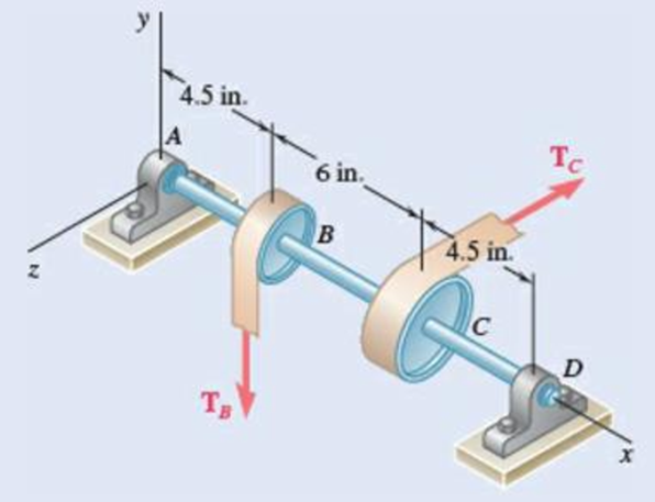
Fig. P4.F5
Expert Solution & Answer
Want to see the full answer?
Check out a sample textbook solution
Students have asked these similar questions
PROBLEM 3.23
3.23 Under normal operating condi-
tions a motor exerts a torque of
magnitude TF at F. The shafts
are made of a steel for which
the allowable shearing stress is
82 MPa and have diameters of
dCDE=24 mm and dFGH = 20
mm. Knowing that rp = 165
mm and rg114 mm, deter-
mine the largest torque TF
which may be exerted at F.
TF
F
rG-
rp
B
CH
TE
E
1. (16%) (a) If a ductile material fails under pure torsion, please explain the failure
mode and describe the observed plane of failure.
(b) Suppose a prismatic beam is subjected to equal and opposite couples as shown
in Fig. 1. Please sketch the deformation and the stress distribution of the cross
section.
M
M
Fig. 1
(c) Describe the definition of the neutral axis.
(d) Describe the definition of the modular ratio.
using the theorem of three moments, find all the moments, I only need concise calculations with minimal explanations. The correct answers are provided at the bottom
Chapter 4 Solutions
Vector Mechanics for Engineers: Statics and Dynamics
Ch. 4.1 - Two crates, each of mass 350 kg, are placed as...Ch. 4.1 - A lever AB is hinged at C and attached to a...Ch. 4.1 - A light rod AD is supported by frictionless pegs...Ch. 4.1 - A tension of 20 N is maintained in a tape as it...Ch. 4.1 - A gardener uses a 60 N wheelbarrow to transport a...Ch. 4.1 - The gardener of Prob. 4.1 wishes to transport a...Ch. 4.1 - A 2100-lb tractor is used to lift 900 lb of grave....Ch. 4.1 - For the beam and loading shown, determine (a) the...Ch. 4.1 - A load of lumber of weight W = 25 kN is being...Ch. 4.1 - A load of lumber of weight W = 25 kN is being...
Ch. 4.1 - Prob. 4.7PCh. 4.1 - Prob. 4.8PCh. 4.1 - Three loads are applied as shown to a light beam...Ch. 4.1 - Prob. 4.10PCh. 4.1 - Prob. 4.11PCh. 4.1 - For the beam of Sample Prob. 4.2, determine the...Ch. 4.1 - The maximum allowable value of each of the...Ch. 4.1 - For the beam and loading shown, determine the...Ch. 4.1 - 4.15 Two links AB and DE are connected by a bell...Ch. 4.1 - Prob. 4.16PCh. 4.1 - 4.17 The required tension in cable AB is 200 lb....Ch. 4.1 - Prob. 4.18PCh. 4.1 - The bracket BCD is hinged at C and attached to a...Ch. 4.1 - The ladder AB, of length L and weight W, can be...Ch. 4.1 - 4.21 The 40-ft boom AB weighs 2 kips; the distance...Ch. 4.1 - A lever AB is hinged at C and attached to a...Ch. 4.1 - 4.23 and 4.24 For each of the plates and loadings...Ch. 4.1 - Prob. 4.24PCh. 4.1 - A rod AB, hinged at A and attached at B to cable...Ch. 4.1 - Prob. 4.26PCh. 4.1 - Prob. 4.27PCh. 4.1 - Determine the reactions at A and C when (a) = 0,...Ch. 4.1 - Prob. 4.29PCh. 4.1 - Prob. 4.30PCh. 4.1 - Neglecting friction, determine the tension in...Ch. 4.1 - Fig. P4.31 and P4.32 4.32 Neglecting friction,...Ch. 4.1 - PROBLEM 4.33 A force P of magnitude 90 lb is...Ch. 4.1 - PROBLEM 4.34 Solve Problem 4,33 for a = 6 in,...Ch. 4.1 - Prob. 4.35PCh. 4.1 - PROBLEM 4.36 A light bar AD is suspended from a...Ch. 4.1 - Prob. 4.37PCh. 4.1 - Prob. 4.38PCh. 4.1 - Prob. 4.39PCh. 4.1 - Prob. 4.40PCh. 4.1 - Prob. 4.41PCh. 4.1 - Prob. 4.42PCh. 4.1 - The rig shown consists of a 1200-lb horizontal...Ch. 4.1 - Fig. P4.43 4.44 For the rig and crate of Prob....Ch. 4.1 - Prob. 4.45PCh. 4.1 - Knowing that the tension in wire BD is 1300 N,...Ch. 4.1 - Prob. 4.47PCh. 4.1 - Beam AD carries the two 40-lb loads shown. The...Ch. 4.1 - Fig. P4.48 and P4.49 4.49 For the beam and loading...Ch. 4.1 - Prob. 4.50PCh. 4.1 - A uniform rod AB with a length of l and weight of...Ch. 4.1 - Rod AD is acted upon by a vertical force P at end...Ch. 4.1 - A slender rod AB with a weigh of W is attached to...Ch. 4.1 - 4.54 and 4.55 A vertical load P is applied at end...Ch. 4.1 - 4.54 and 4.55 A vertical load P is applied at end...Ch. 4.1 - A collar B with a weight of W can move freely...Ch. 4.1 - A 400-lb weight is attached at A to the lever...Ch. 4.1 - Prob. 4.58PCh. 4.1 - Prob. 4.59PCh. 4.1 - Prob. 4.60PCh. 4.2 - A 500-lb cylindrical tank, 8 ft in diameter, is to...Ch. 4.2 - 4.62 Determine the reactions at A and B when a =...Ch. 4.2 - Prob. 4.63PCh. 4.2 - Prob. 4.64PCh. 4.2 - Determine the reactions at B and C when a = 30 mm.Ch. 4.2 - Prob. 4.66PCh. 4.2 - Determine the reactions at B and D when b = 60 mm....Ch. 4.2 - For the frame and loading shown, determine the...Ch. 4.2 - A 50-kg crate is attached to the trolley-beam...Ch. 4.2 - One end of rod AB rests in the corner A and the...Ch. 4.2 - For the boom and loading shown, determine (a) the...Ch. 4.2 - Prob. 4.72PCh. 4.2 - Prob. 4.73PCh. 4.2 - Prob. 4.74PCh. 4.2 - Rod AB is supported by a pin and bracket at A and...Ch. 4.2 - Solve Prob. 4.75, assuming that the 170-N force...Ch. 4.2 - Prob. 4.77PCh. 4.2 - Using the method of Sec. 4.2B, solve Prob. 4.22....Ch. 4.2 - Knowing that = 30, determine the reaction (a) at...Ch. 4.2 - Knowing that = 60, determine the reaction (a) at...Ch. 4.2 - Determine the reactions at A and B when = 50....Ch. 4.2 - Determine the reactions at A and B when = 80.Ch. 4.2 - Rod AB is bent into the shape of an arc of circle...Ch. 4.2 - A slender rod of length L is attached to collars...Ch. 4.2 - An 8-kg slender rod of length L is attached to...Ch. 4.2 - Prob. 4.86PCh. 4.2 - A slender rod BC with a length of L and weight W...Ch. 4.2 - A thin ring with a mass of 2 kg and radius r = 140...Ch. 4.2 - A slender rod with a length of L and weight W is...Ch. 4.2 - Fig. P4.89 4.90 Knowing that for the rod of Prob....Ch. 4.3 - Two tape spools are attached to an axle supported...Ch. 4.3 - Prob. 4.6FBPCh. 4.3 - A 20-kg cover for a roof opening is hinged at...Ch. 4.3 - Prob. 4.91PCh. 4.3 - Prob. 4.92PCh. 4.3 - A small winch is used to raise a 120-lb load. Find...Ch. 4.3 - Prob. 4.94PCh. 4.3 - A 250 400-mm plate of mass 12 kg and a...Ch. 4.3 - Prob. 4.96PCh. 4.3 - Prob. 4.97PCh. 4.3 - Prob. 4.98PCh. 4.3 - Prob. 4.99PCh. 4.3 - Prob. 4.100PCh. 4.3 - PROBLEM 4.101 Two steel pipes AB and BC, each...Ch. 4.3 - PROBLEM 4.102 For the pipe assembly of Problem...Ch. 4.3 - PROBLEM 4.103 The 24-lb square plate shown is...Ch. 4.3 - PROBLEM 4.104 The table shown weighs 30 lb and has...Ch. 4.3 - PROBLEM 4.105 A 10-ft boom is acted upon by the...Ch. 4.3 - PROBLEM 4.106 The 6-m pole ABC is acted upon by a...Ch. 4.3 - PROBLEM 4.107 Solve Problem 4.106 for a = 1.5 m....Ch. 4.3 - Prob. 4.108PCh. 4.3 - Prob. 4.109PCh. 4.3 - Prob. 4.110PCh. 4.3 - PROBLEM 4.111 A 48-in. boom is held by a...Ch. 4.3 - PROBLEM 4.112 Solve Problem 4.111, assuming that...Ch. 4.3 - PROBLEM 4.114 The bent rod ABEF is supported by...Ch. 4.3 - The bent rod ABEF is supported by bearings at C...Ch. 4.3 - The horizontal platform ABCD weighs 60 lb and...Ch. 4.3 - Prob. 4.116PCh. 4.3 - Prob. 4.117PCh. 4.3 - Solve Prob. 4.117, assuming that cable DCE is...Ch. 4.3 - PROBLEM 4.119 Solve Prob. 4.113, assuming that the...Ch. 4.3 - PROBLEM 4.120 Solve Prob. 4.115, assuming that the...Ch. 4.3 - PROBLEM 4.121 The assembly shown is used to...Ch. 4.3 - Prob. 4.122PCh. 4.3 - Prob. 4.123PCh. 4.3 - Prob. 4.124PCh. 4.3 - Prob. 4.125PCh. 4.3 - Prob. 4.126PCh. 4.3 - Prob. 4.127PCh. 4.3 - Prob. 4.128PCh. 4.3 - Frame ABCD is supported by a ball-and-socket joint...Ch. 4.3 - Prob. 4.130PCh. 4.3 - The assembly shown consists of an 80-mm rod AF...Ch. 4.3 - Prob. 4.132PCh. 4.3 - The frame ACD is supported by ball-and-socket...Ch. 4.3 - Prob. 4.134PCh. 4.3 - Prob. 4.135PCh. 4.3 - Prob. 4.136PCh. 4.3 - Prob. 4.137PCh. 4.3 - Prob. 4.138PCh. 4.3 - Prob. 4.139PCh. 4.3 - Prob. 4.140PCh. 4.3 - Prob. 4.141PCh. 4 - Prob. 4.142RPCh. 4 - 4. 143 The lever BCD is hinged at C and attached...Ch. 4 - Prob. 4.144RPCh. 4 - Neglecting friction and the radius of the pulley,...Ch. 4 - Prob. 4.146RPCh. 4 - PROBLEM 4.147 A slender rod AB, of weight W, is...Ch. 4 - PROBLEM 4.148 Determine the reactions at A and B...Ch. 4 - Prob. 4.149RPCh. 4 - PROBLEM 4.150 A 200-mm lever and a 240-mm-diameter...Ch. 4 - Prob. 4.151RPCh. 4 - Prob. 4.152RPCh. 4 - A force P is applied to a bent rod ABC, which may...
Knowledge Booster


Learn more about
Need a deep-dive on the concept behind this application? Look no further. Learn more about this topic, mechanical-engineering and related others by exploring similar questions and additional content below.Similar questions
- PROBLEM 3.46 The solid cylindrical rod BC of length L = 600 mm is attached to the rigid lever AB of length a = 380 mm and to the support at C. When a 500 N force P is applied at A, design specifications require that the displacement of A not exceed 25 mm when a 500 N force P is applied at A For the material indicated determine the required diameter of the rod. Aluminium: Tall = 65 MPa, G = 27 GPa. Aarrow_forwardFind the equivalent mass of the rocker arm assembly with respect to the x coordinate. k₁ mi m2 k₁arrow_forward2. Figure below shows a U-tube manometer open at both ends and containing a column of liquid mercury of length l and specific weight y. Considering a small displacement x of the manometer meniscus from its equilibrium position (or datum), determine the equivalent spring constant associated with the restoring force. Datum Area, Aarrow_forward
- 1. The consequences of a head-on collision of two automobiles can be studied by considering the impact of the automobile on a barrier, as shown in figure below. Construct a mathematical model (i.e., draw the diagram) by considering the masses of the automobile body, engine, transmission, and suspension and the elasticity of the bumpers, radiator, sheet metal body, driveline, and engine mounts.arrow_forward3.) 15.40 – Collar B moves up at constant velocity vB = 1.5 m/s. Rod AB has length = 1.2 m. The incline is at angle = 25°. Compute an expression for the angular velocity of rod AB, ė and the velocity of end A of the rod (✓✓) as a function of v₂,1,0,0. Then compute numerical answers for ȧ & y_ with 0 = 50°.arrow_forward2.) 15.12 The assembly shown consists of the straight rod ABC which passes through and is welded to the grectangular plate DEFH. The assembly rotates about the axis AC with a constant angular velocity of 9 rad/s. Knowing that the motion when viewed from C is counterclockwise, determine the velocity and acceleration of corner F.arrow_forward
arrow_back_ios
SEE MORE QUESTIONS
arrow_forward_ios
Recommended textbooks for you
 Elements Of ElectromagneticsMechanical EngineeringISBN:9780190698614Author:Sadiku, Matthew N. O.Publisher:Oxford University Press
 Mechanics of Materials (10th Edition)Mechanical EngineeringISBN:9780134319650Author:Russell C. HibbelerPublisher:PEARSON
 Thermodynamics: An Engineering ApproachMechanical EngineeringISBN:9781259822674Author:Yunus A. Cengel Dr., Michael A. BolesPublisher:McGraw-Hill Education
 Control Systems EngineeringMechanical EngineeringISBN:9781118170519Author:Norman S. NisePublisher:WILEY
 Mechanics of Materials (MindTap Course List)Mechanical EngineeringISBN:9781337093347Author:Barry J. Goodno, James M. GerePublisher:Cengage Learning
 Engineering Mechanics: StaticsMechanical EngineeringISBN:9781118807330Author:James L. Meriam, L. G. Kraige, J. N. BoltonPublisher:WILEY
Elements Of Electromagnetics
Mechanical Engineering
ISBN:9780190698614
Author:Sadiku, Matthew N. O.
Publisher:Oxford University Press
Mechanics of Materials (10th Edition)
Mechanical Engineering
ISBN:9780134319650
Author:Russell C. Hibbeler
Publisher:PEARSON
Thermodynamics: An Engineering Approach
Mechanical Engineering
ISBN:9781259822674
Author:Yunus A. Cengel Dr., Michael A. Boles
Publisher:McGraw-Hill Education
Control Systems Engineering
Mechanical Engineering
ISBN:9781118170519
Author:Norman S. Nise
Publisher:WILEY
Mechanics of Materials (MindTap Course List)
Mechanical Engineering
ISBN:9781337093347
Author:Barry J. Goodno, James M. Gere
Publisher:Cengage Learning
Engineering Mechanics: Statics
Mechanical Engineering
ISBN:9781118807330
Author:James L. Meriam, L. G. Kraige, J. N. Bolton
Publisher:WILEY
BEARINGS BASICS and Bearing Life for Mechanical Design in 10 Minutes!; Author: Less Boring Lectures;https://www.youtube.com/watch?v=aU4CVZo3wgk;License: Standard Youtube License