
Videos
(a)
Find whether the plate is completely, partially, or improperly constrained.
(a)
Answer to Problem 4.59P
The plate in figure 1 is
The plate figure 2 is
The plate figure 3 is
The plate figure 4 is
The plate figure 5 is
The plate figure 6 is
The plate figure 7 is
The plate figure 8 is
Explanation of Solution
Given information:
The size of the identical plates is
Number of plates is 8.
The mass of each plate is
Calculation:
Find the weight (W) of the plate using the relation.
Here, the acceleration due to gravity is g.
Consider the acceleration due to gravity as
Substitute 40 kg for m and
Figure 1:
Show the free-body diagram of the Figure 1.
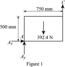
The three reactions in the plate behave like non-concurrent and non-parallel force system.
The plate in figure 1 is
Figure 2:
Show the free-body diagram of the Figure 2.
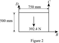
The three reactions in the plate behave like non-concurrent and non-parallel force system.
The plate figure 2 is
Figure 3:
Show the free-body diagram of the Figure 3.
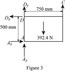
The four reactions in the plate behave like non-concurrent and non-parallel force system.
The plate figure 3 is
Figure 4:
Show the free-body diagram of the Figure 4.
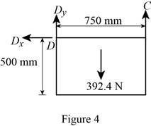
The three reactions in the plate behave like concurrent force system.
The plate figure 4 is
Figure 5:
Show the free-body diagram of the Figure 5.
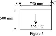
The two reactions in the plate behave like concurrent force system.
The plate figure 5 is
Figure 6:
Show the free-body diagram of the Figure 6.
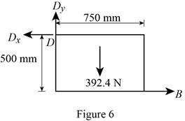
The three reactions in the plate behave like non-concurrent and non-parallel force system.
The plate figure 6 is
Figure 7:
Show the free-body diagram of the Figure 7.
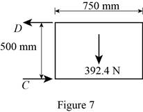
The two reactions in the plate behave like concurrent force system.
The plate figure 7 is
Figure 8:
Show the free-body diagram of the Figure 8.
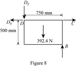
The four reactions in the plate behave like non-concurrent and non-parallel force system.
The plate figure 8 is
(b)
Find whether the reactions are statically determinate or indeterminate.
(b)
Answer to Problem 4.59P
The reactions in figure 1 is
The reactions in figure 2 is
The reactions in figure 3 is
The reactions in figure 4 is
The reactions in figure 5 is
The reactions in figure 6 is
The reactions in figure 7 is
The reactions in figure 8 is
Explanation of Solution
Refer Figure 1:
The equilibrium equations are;
The equilibrium equations are enough to determine the unknown reactions.
The reactions in figure 1 is
Refer Figure 2:
The equilibrium equations are;
The equilibrium equations are enough to determine the unknown reactions.
The reactions in figure 2 is
Refer Figure 3:
The equilibrium equations are;
The equilibrium equations are not enough to determine the unknown reactions.
The reactions in figure 3 is
Refer Figure 4:
The equilibrium equations are;
The equilibrium equations are enough to determine the unknown reactions.
But the plate is improperly constrained and the plate is not in equilibrium.
The reactions in figure 4 is
Refer Figure 5:
The equilibrium equations are;
The equilibrium equations are enough to determine the unknown reactions.
The reactions in figure 5 is
Refer Figure 6:
The equilibrium equations are;
The equilibrium equations are enough to determine the unknown reactions.
The reactions in figure 6 is
Refer Figure 7:
The equilibrium equations are;
The equilibrium equations are enough to determine the unknown reactions.
But the plate is improperly constrained and the plate is not in equilibrium.
The reactions in figure 7 is
Refer Figure 8:
The equilibrium equations are;
The equilibrium equations are not enough to determine the unknown reactions.
The reactions in figure 8 is
(c)
Find whether the equilibrium of the plate is maintained.
(c)
Answer to Problem 4.59P
The reactions in the plate 1 are
The plate 1 is in
The reactions in the plate 2 are
The plate 2 is in
The reactions in the plate 3 are
The plate 3 is in
The plate 4 is in
The reactions in the plate 5 are
The plate 5 is in
The reactions in the plate 6 are
The plate 6 is in
The plate 7 is in
The reactions in the plate 8 are
The plate 8 is in
Explanation of Solution
Refer Figure 1:
The equilibrium equations are;
Take moment about point A.
Resolve the horizontal component of forces.
Resolve the vertical component of forces.
Therefore, the reactions in the plate 1 are
The plate 1 is in
Refer Figure 2:
The equilibrium equations are;
Take moment about point B.
Resolve the horizontal component of forces.
Resolve the vertical component of forces.
Therefore, the reactions in the plate 2 are
The plate 2 is in
Refer Figure 3:
The equilibrium equations are;
Take moment about point A.
Resolve the horizontal component of forces.
Resolve the vertical component of forces.
Therefore, the reactions in the plate 3 are
The plate 3 is in
Refer Figure 4:
The equilibrium equations are;
The moment about point D is not equal to zero.
The plate 4 is in
Refer Figure 5:
The equilibrium equations are;
Take moment about point A.
Resolve the vertical component of forces.
Therefore, the reactions in the plate 5 are
The plate 5 is in
Refer Figure 6:
The equilibrium equations are;
Take moment about point A.
Resolve the vertical component of forces.
Resolve the horizontal component of forces.
Find the resultant force at D;
Find the angle
Therefore, the reactions in the plate 6 are
The plate 6 is in
Refer Figure 7:
The equilibrium equations are;
The plate 7 is in
Refer Figure 8:
The equilibrium equations are;
Take moment about point D.
Resolve the vertical component of forces.
Resolve the horizontal component of forces.
Therefore, the reactions in the plate 8 are
The plate 8 is in
Want to see more full solutions like this?
Chapter 4 Solutions
VECTOR MECH...,STAT.+DYNA.(LL)-W/ACCESS


- Auto Controls Hand sketch the root Focus of the following transfer function How many asymptotes are there ?what are the angles of the asymptotes?Does the system remain stable for all values of K NO COPIED SOLUTIONSarrow_forward-400" 150" in Datum 80" 90" -280"arrow_forwardUsing hand drawing both of themarrow_forward
- A 10-kg box is pulled along P,Na rough surface by a force P, as shown in thefigure. The pulling force linearly increaseswith time, while the particle is motionless att = 0s untilit reaches a maximum force of100 Nattimet = 4s. If the ground has staticand kinetic friction coefficients of u, = 0.6 andHU, = 0.4 respectively, determine the velocityof the A 1 0 - kg box is pulled along P , N a rough surface by a force P , as shown in the figure. The pulling force linearly increases with time, while the particle is motionless at t = 0 s untilit reaches a maximum force of 1 0 0 Nattimet = 4 s . If the ground has static and kinetic friction coefficients of u , = 0 . 6 and HU , = 0 . 4 respectively, determine the velocity of the particle att = 4 s .arrow_forwardCalculate the speed of the driven member with the following conditions: Diameter of the motor pulley: 4 in Diameter of the driven pulley: 12 in Speed of the motor pulley: 1800 rpmarrow_forward4. In the figure, shaft A made of AISI 1010 hot-rolled steel, is welded to a fixed support and is subjected to loading by equal and opposite Forces F via shaft B. Stress concentration factors K₁ (1.7) and Kts (1.6) are induced by the 3mm fillet. Notch sensitivities are q₁=0.9 and qts=1. The length of shaft A from the fixed support to the connection at shaft B is 1m. The load F cycles from 0.5 to 2kN and a static load P is 100N. For shaft A, find the factor of safety (for infinite life) using the modified Goodman fatigue failure criterion. 3 mm fillet Shaft A 20 mm 25 mm Shaft B 25 mmarrow_forward
 International Edition---engineering Mechanics: St...Mechanical EngineeringISBN:9781305501607Author:Andrew Pytel And Jaan KiusalaasPublisher:CENGAGE L